Clamp spring type self-locking cable cover on electric connector

An electrical connector and cable cover technology, applied in the field of spring-type self-locking cable cover, can solve the problems of limited application occasions, low reliability of anti-loosening, large space occupation, etc., and achieves high applicability, reduced weight and The effect of volume and space reduction

Inactive Publication Date:
View PDF3 Cites 7 Cited by
  • Summary
  • Abstract
  • Description
  • Claims
  • Application Information

AI Technical Summary

Problems solved by technology

This requires an innovative improvement in the structure of the existing self-locking cable cover to solve the problems of the existing self-locking cable cover occupying a large space, low reliability of anti-loosening, and limited application occasions

Method used


Image

  • Clamp spring type self-locking cable cover on electric connector
  • Clamp spring type self-locking cable cover on electric connector
  • Clamp spring type self-locking cable cover on electric connector

Examples


Embodiment Construction

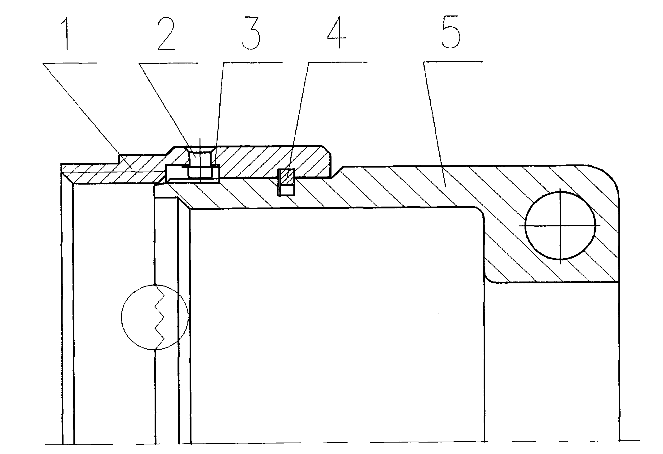
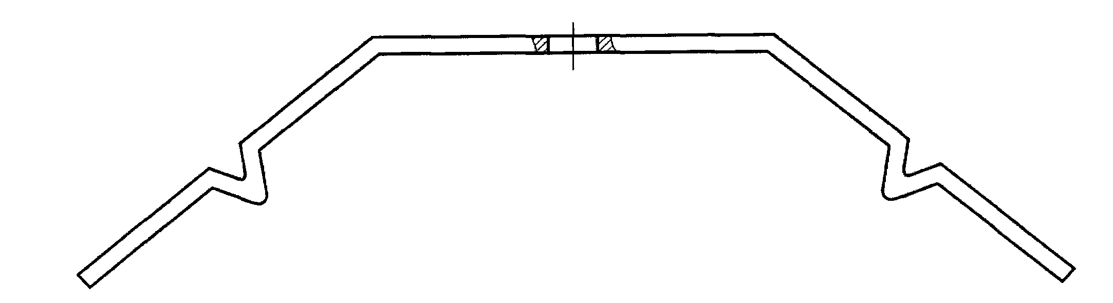
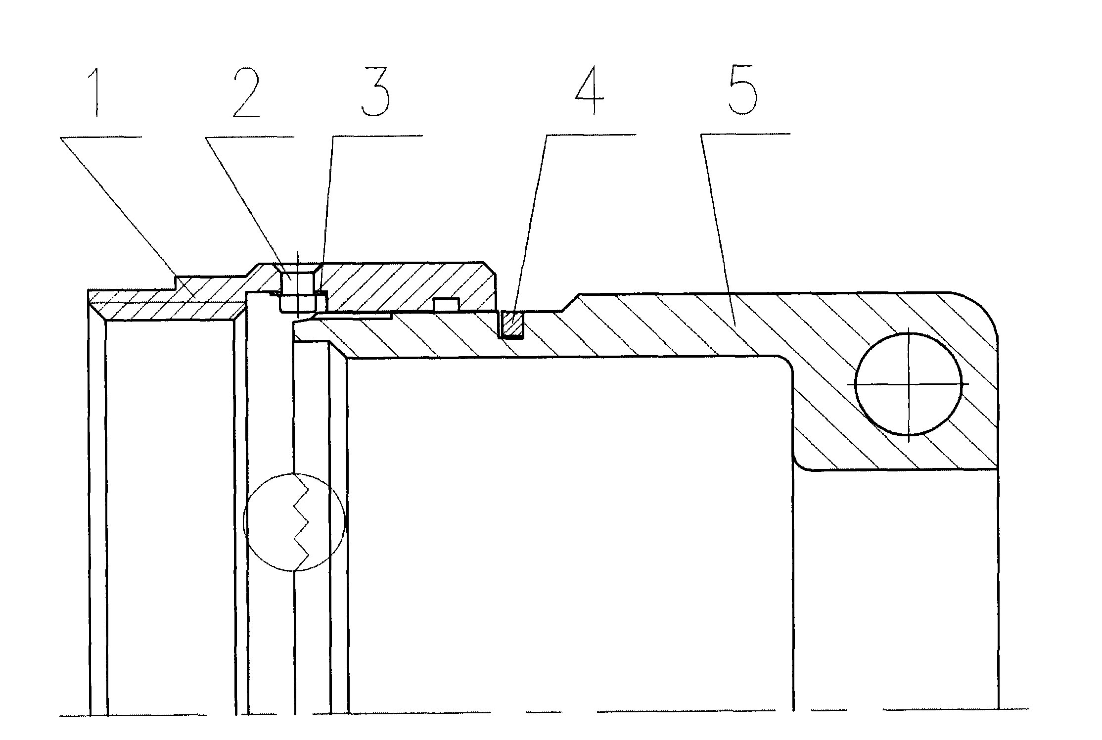
[0020] The circlip type self-locking cable cover of the present invention designs a groove in the connecting nut and a circlip with tines at the same time, and designs convex teeth on the cable cover element to engage with the tines to realize self-locking . The circlip is the key elastic element for anti-loosening and self-locking. It can be made of beryllium bronze, such as QBe2 and C17300. The circlip is fixed in the inner groove of the connecting nut by means of bayonet riveting, and the connecting nut is connected with the clamping ring. The cable cover elements are fixed together, and only a normal fit gap needs to be reserved between the connection nut and the cable cover element, and the connection nut can rotate freely relative to the cable cover element.

[0021] Such as figure 1 As shown, the embodiment of the circlip type self-locking cable cover of the present invention includes a connection nut 1, a bayonet pin 2, a clip spring 3, a clip ring 4 and a cable cover...


PUM


Abstract

A clamp spring type self-locking cable cover on an electric connector comprises a connecting nut, clamp pins, clamp springs, a clamp ring and a cable cover element. The clamp springs are fixed into clamp spring grooves of the connecting nut via the clamp pins, and the cable cover element is mounted in a clamp ring groove of the connecting nut via the clamp ring. The clamp spring type self-locking cable cover has the advantages of high looseness prevention reliability and small occupied structural space.

Description

technical field [0001] The invention relates to a spring-type self-locking cable cover with anti-loosening function and small space occupation, which can be used as a tail attachment for effectively clamping and supporting cables on an electrical connector under mechanical environment conditions such as strong impact. Background technique [0002] At the tail of the electrical connector, that is, the terminal part of the electrical connector, it is generally necessary to design a tail accessory such as a cable cover. The force on the connection or welding part will cause disconnection fault at the cable terminal. [0003] The commonly used spring + steel ball type self-locking cable cover structure is designed with evenly distributed counterbores on the connecting nut to install springs and steel balls. The structure is more complicated and takes up a large structural space. The applicability of other applications is not high. The use of a cable cover with a fuse for anti-...

Claims


Application Information

Patent Timeline
Patent Type & Authority Applications(China)
IPC IPC(8): H01R13/58
Inventor 陈振宇陈丹良吴仕锋周健锋
Why Eureka
Try Eureka