Improved buffering and current limiting circuit for direct-current power source of LED lamp

A technology of DC power supply and current limiting circuit, which is applied in the direction of electric lamp circuit layout, electric light source, circuit device, etc., can solve the problems of large pressure difference, achieve the effect of prolonging the service life, preventing breakdown or abnormal aging

Inactive Publication Date: 2013-04-03
EAGLERISE ELECTRIC & ELECTRONICS (CHINA) CO LTD
View PDF4 Cites 6 Cited by
  • Summary
  • Abstract
  • Description
  • Claims
  • Application Information

AI Technical Summary

Problems solved by technology

This circuit effectively suppresses the impact circuit generated at the moment of the LED load switch, but in the circuit with a large voltage difference, after using and using the instrument to detect, it is found that after the switch is closed, because the voltage at both ends of R3 is within the equivalent The peak pulse current will still be generated when the switch control circuit is turned on

Method used


Image

  • Improved buffering and current limiting circuit for direct-current power source of LED lamp
  • Improved buffering and current limiting circuit for direct-current power source of LED lamp
  • Improved buffering and current limiting circuit for direct-current power source of LED lamp

Examples


Embodiment Construction

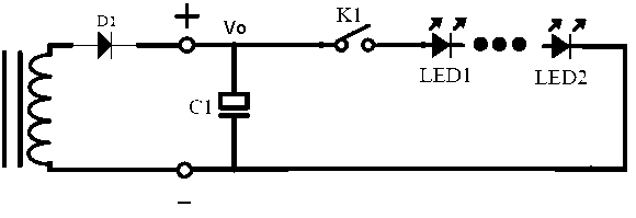
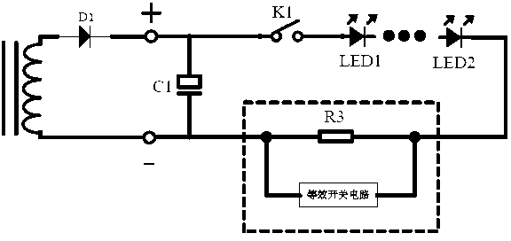
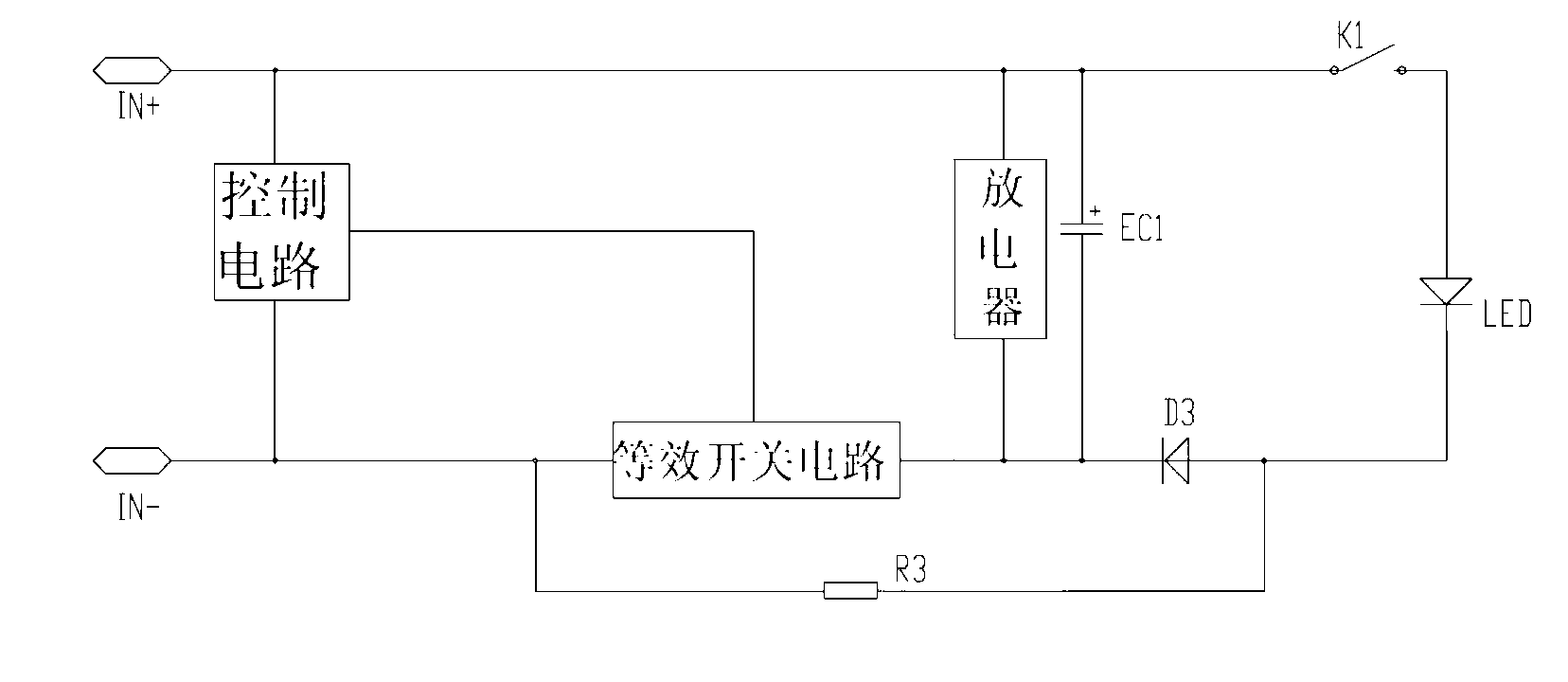
[0015] like image 3 and Figure 4 As shown, a buffer current limiting circuit for the DC power supply of LED lighting lamps, the DC power supply circuit includes a rectification circuit D1 and a controller connected in parallel at the output end of the rectification circuit D1 for controlling the equivalent switching circuit. The control circuit of the DC power supply circuit, the output load end of the DC power supply circuit includes a control switch K1 and more than one LED light in series; a buffer current limiting circuit is set at the output end of the DC power supply circuit, and the buffer current limiting circuit includes a limiter Flow resistance R3 and equivalent switch circuit. Wherein the current limiting resistor R3 is connected in series with the negative pole of the output circuit of the DC power supply circuit, and an equivalent switch control circuit is connected in parallel at both ends of the current limiting resistor R3, and the equivalent switch contro...


PUM


Abstract

An improved buffering and current limiting circuit for a direct-current power source of an LED lamp is characterized in that a buffering capacitor EC1 and a discharger are parallelly connected between an LED load end and an equivalent switch control circuit, the discharger is used for discharging to the buffering capacitor EC1, and a reverse diode D3 is serially connected to a loop formed by the buffering capacitor EC1 and a current limiting resistor R3. Influences of secondary spike pulse current on the LED lamp circuit in starting can be prevented while the buffering capacitor EC1 can be prevented from being charged by the aid of the current limiting resistor R3. Therefore, the improved buffering and current limiting circuit can be widely applied to power source control systems of LED lamps.

Description

technical field [0001] The invention relates to a control circuit of a direct current power supply of an LED lamp, in particular to a start-up control circuit of a direct current power supply of an LED lamp. Background technique [0002] The existing LED lighting DC power supply control circuit, such as figure 1 As shown, it includes a rectification circuit D1 and a filter capacitor C1 connected in parallel to the output end of the rectification circuit D1. The load end of the rectification circuit D1 is connected to a control switch K1 and a light-emitting LED lamp. In this kind of circuit, take one to three 1W LED constant-current switching power supplies as an example: first turn on the power supply, and before the switch K1 is closed, the charging voltage across the capacitor C1 is about Vo. When the load is more than one LED lamp, just after the switch K1 is turned on, it can be known from the formula I∝C×du / dt that the voltage at both ends of the capacitor C1 will qui...

Claims


Application Information

Patent Timeline
IPC IPC(8): H05B37/02H02H9/02
Inventor 肖俊承张铁镭
Owner EAGLERISE ELECTRIC & ELECTRONICS (CHINA) CO LTD
Why Eureka
Try Eureka