
Centrifugal force pendulum device

A technology of centrifugal pendulum and pendulum mass, which is used in spring/shock absorber, vibration suppression adjustment, mechanical equipment, etc., to achieve the effect of reducing structural space requirements

Inactive Publication Date: 2013-04-03
SCHAEFFLER TECH AG & CO KG
View PDF9 Cites 9 Cited by
  • Summary
  • Abstract
  • Description
  • Claims
  • Application Information

AI Technical Summary

Problems solved by technology

On the other hand, the suspension of the pendulum mass on the swivel joint requires a lot of installation space

Method used


Image

  • Centrifugal force pendulum device
  • Centrifugal force pendulum device
  • Centrifugal force pendulum device

Examples


Embodiment Construction

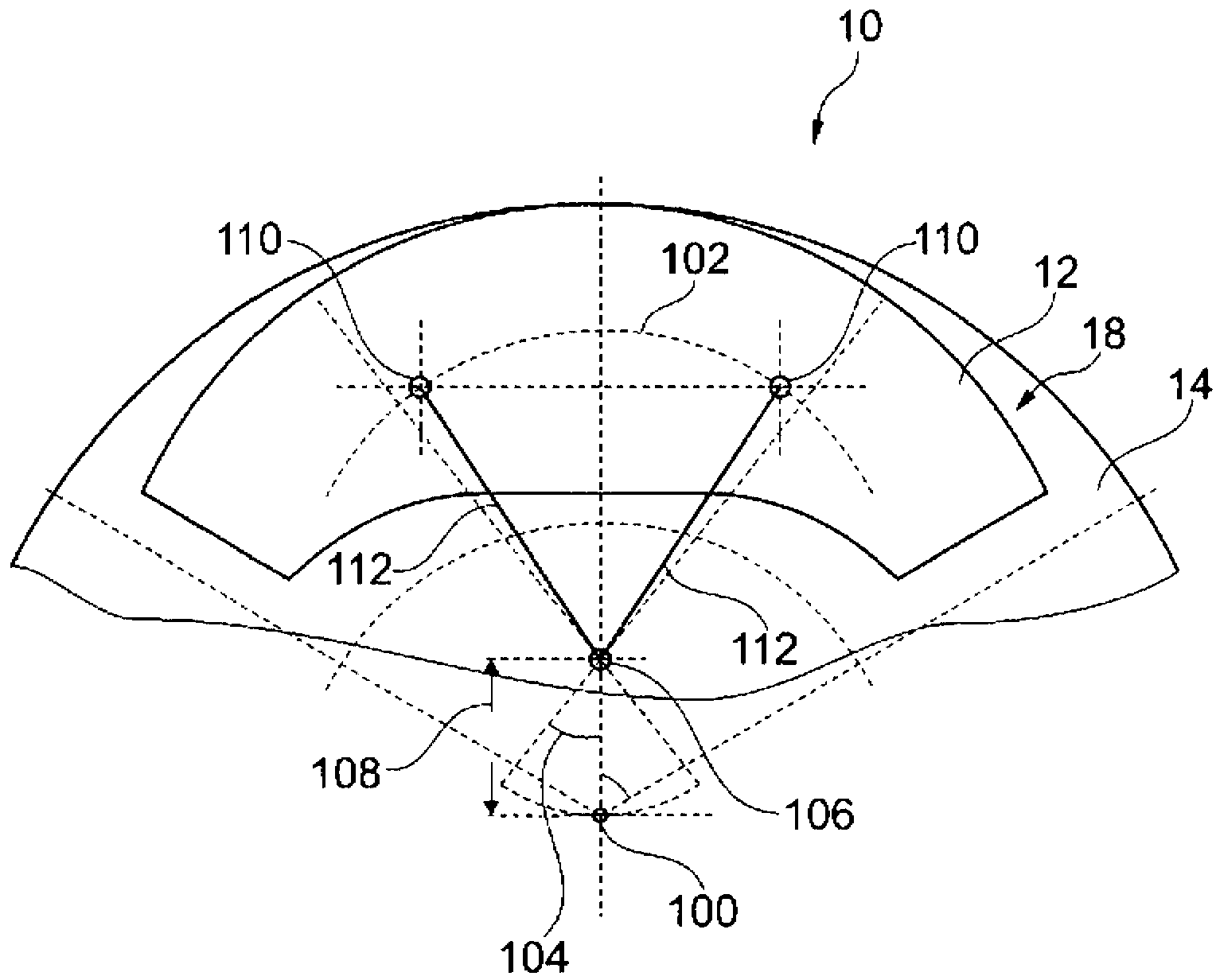
[0030] FIG. 1 shows a detail of a plan view of a centrifugal pendulum device 10 in a special embodiment of the invention in the zero state. In this zero state, the pendulum mass 12 is not deflected relative to the pendulum mass carrier 14 and is in a state of minimum potential energy, that is to say radially most in an external location. Pendulum mass 12 is connected to the pendulum mass on the opposite side of pendulum mass 14 and is not visible in this illustration to form a pendulum mass pair 18 .

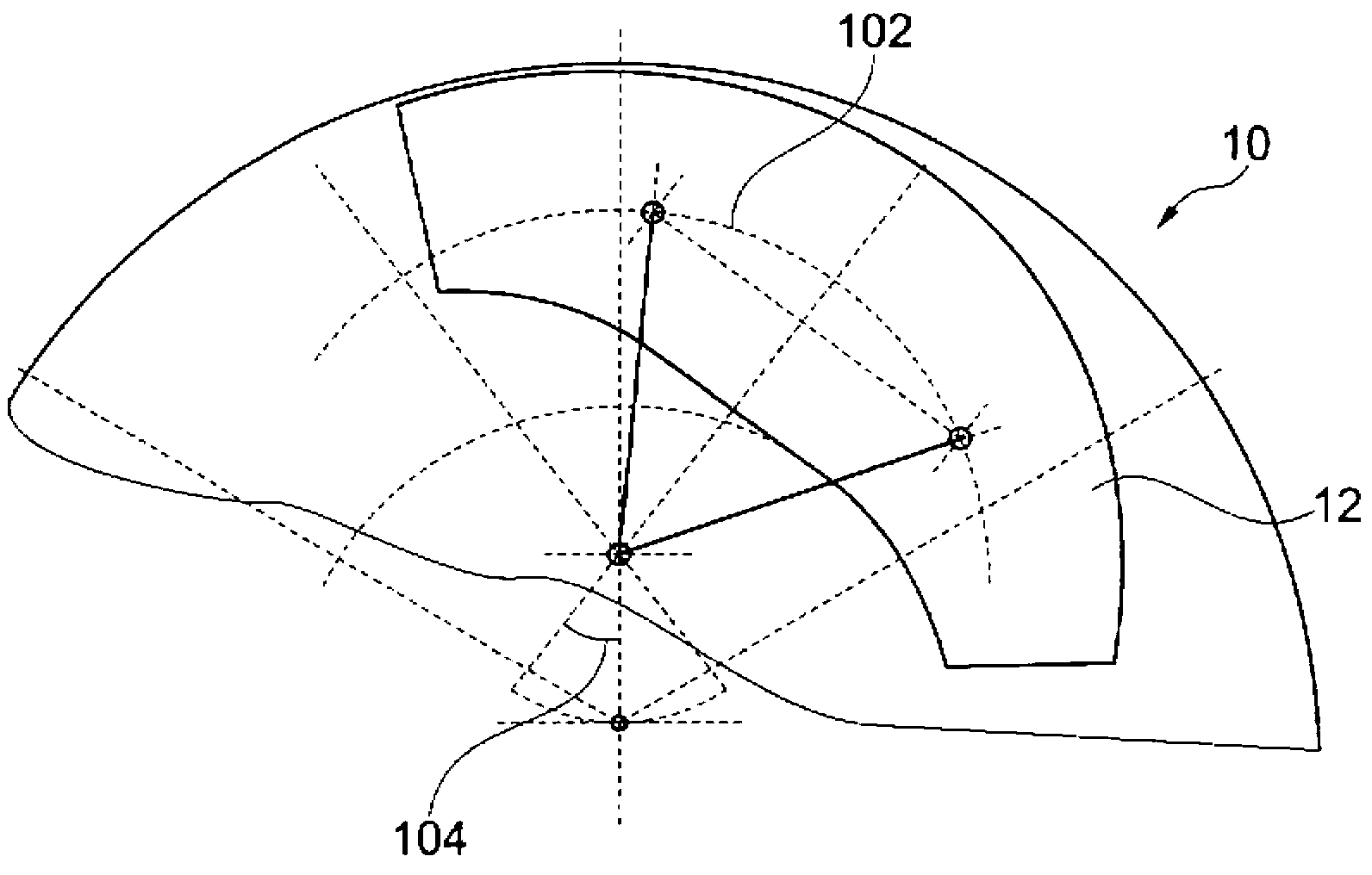
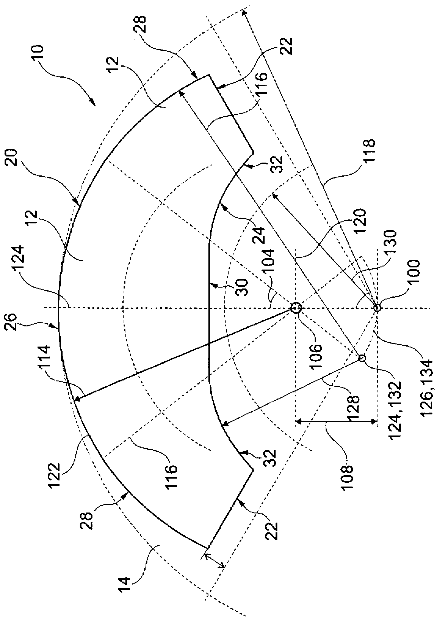
[0031]The pendulum mass 12 can pivot relative to the pendulum mass carrier 14 up to a maximum pivot angle 104 along a pendulum track 102 formed by a cutout in the pendulum mass carrier 14 by means of two rolling elements that can roll in the cutout. The pendulum track 102 has the shape of a circular arc, wherein the axis of rotation 106 as the center of the circular arc is stationary relative to the pendulum mass carrier 14 and does not change when the pendulum mass 12 moves al...


PUM


Abstract

The invention relates to a centrifugal force pendulum device with pendulum masses which are arranged axially on both sides on a pendulum mass carrier, which is rotatable about an axis of rotation, and form a pair of pendulum masses, wherein the pair of pendulum masses can be pivoted to a limited extent along a circular-arc-shaped pendulum path in relation to the pendulum mass carrier with the aid of at least two rolling elements which are rollable in a single cutout or in different cutouts in the pendulum mass carrier, and wherein the pendulum path has an axis of rotation which is positionally fixed with respect to the pendulum mass carrier and is at a radial distance from the pendulum mass.

Description

technical field [0001] The invention relates to a centrifugal pendulum device having the features of the preamble of claim 1 . Background technique [0002] Such a centrifugal pendulum device that functions in the drive train of a motor vehicle is known from DE 10 2006 028 556 A1. This centrifugal pendulum device for eliminating and / or damping torsional vibrations in a drive train comprises a pendulum mass carrier rotatable around a rotational axis and at least one pendulum mass pair arranged on the pendulum mass carrier, said A pendulum mass pair comprises two axially opposite pendulum masses fastened on both sides of the pendulum mass, which are connected to one another by means of fastening elements passing through recesses in the pendulum mass carrier. [0003] The pair of pendulum masses is suspended in double strands relative to the pendulum mass carrier by means of two rolling elements, each of which is located in a cutout in the pendulum mass carrier and each of the...

Claims


Application Information

Patent Timeline
Patent Type & Authority Applications(China)
IPC IPC(8): F16F15/14
CPCF16F15/14F16F15/145Y10T74/2128
Inventor E·克雷默P·莫夫拉扎达
Owner SCHAEFFLER TECH AG & CO KG
Learn More