
Clamping device

A device and clamping part technology, applied in the direction of surgical robots, etc., can solve the problems of increased surgical risk, difficult assembly, and narrow operating environment for minimally invasive surgery

Active Publication Date: 2018-06-12
HIWIN TECH
View PDF8 Cites 3 Cited by
  • Summary
  • Abstract
  • Description
  • Claims
  • Application Information

AI Technical Summary

Problems solved by technology

However, the large number of components and complex mechanism will inevitably lead to difficult assembly, and the problem of excessive precision error of the assembled product
In addition, the main problem with the use of steel wires is that the steel wires are stretchable and elastic. After a long period of use, the steel wires must be adjusted or even replaced, and there is still room for improvement in the stability of the clamping force of the clamping device driven by the steel wires.
[0004] In addition, the operating range of the clamping device is also the design focus of minimally invasive surgical instruments. The reason is that the operating environment of minimally invasive surgery is quite narrow. If the range of motion of the clamping device is insufficient, it is necessary to replace the device to meet the surgical needs. It will not only increase the operation time and inconvenience, but also increase the risk of operation

Method used


Image

  • Clamping device
  • Clamping device
  • Clamping device

Examples


Embodiment Construction

[0033] In order to make the object, technical solution and advantages of the present invention clearer, the present invention will be further described in detail below in conjunction with specific embodiments and with reference to the accompanying drawings.

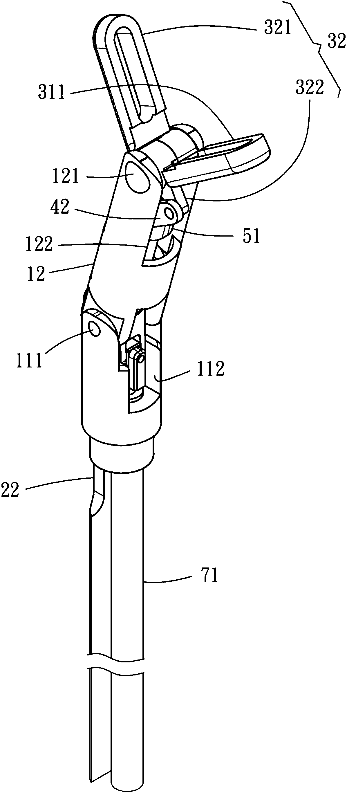
[0034] Such as Figure 1-4 As shown, a clamping device provided by the first preferred embodiment of the present invention includes: a first pipe body 11, a second pipe body 12, a first rod 21, a second rod 22, a A first claw arm 31, a second claw arm 32, a third rod 41, a fourth rod 42, a nut 51, a screw rod 61, a first universal joint 62, a fifth rod 63, a first Two universal joints 64 and a driving rod 71.

[0035] The first tube body 11 has a first connecting end 111 and extends axially from the first connecting end 111 to form a first accommodating groove 112 .

[0036] The second pipe body 12 is pivotally connected to the first pipe body 11 at the first connecting end 111 . The second tube body 12 has a second co...


PUM


Abstract

The invention relates to a clamping device. The clamping device comprises a first pipe body, a second pipe body, a first rod pivoted to the second pipe body, a second rod pivoted to the first rod, a first claw arm, a second claw arm, a third rod, a fourth rod, a nut and a screw, wherein first pipe body and the second pipe body are pivoted to each other, the first claw arm is provided with a firstclamping part and a first connecting part, the second claw arm is provided with a second clamping part and a second connecting part, the first claw arm and the second claw arm are both pivoted to thesecond pipe body, the third rod and the fourth rod are pivoted to the first connecting part and the second connecting part respectively, the nut is pivoted to the third rod and the fourth rod, the screw is in threaded connection with the nut, and the screw is driven by a driving rod through a first universal joint, a fifth rod and a second universal joint. In this way, the driving rod drives the nut to move and controls the first clamping part and the second clamping part to move through the third rod, the fourth rod, the first connecting part and the second connecting part, and then the clamping force can be stably maintained. In addition, the second rod and the first rod are controlled to control the second pipe body, the first clamping part and the second clamping part to swing relativeto the first pipe body.

Description

technical field [0001] The present invention relates to a clamping device, in particular to a clamping device capable of stably maintaining clamping force. Background technique [0002] With the development of medical technology, minimally invasive surgery has become the trend of major surgical operations. Its characteristic is that no huge wounds will be formed after the operation, and the recovery time of patients can be greatly shortened. In laparoscopic and endoscopic surgery, small incisions, punctures, or cannulations are made in the patient's body to allow the insertion of various surgical instruments, such as scissors, dissectors, or retractors, to perform the procedure. [0003] As for the holding device, such as US 6312435, US 6394998, US 6676684 and US 2007 / 0162072A1 patent publications. At present, steel wires are used to pull a large number of terminal micro-mechanisms to achieve the purpose of clamping, so as to achieve the effect of miniaturization and multi-...

Claims


Application Information

Patent Timeline
IPC IPC(8): A61B34/30
Inventor 郭进星刘廷皓王仁政
Owner HIWIN TECH
Learn More