Bottle stopper cleaning machine
A cleaning machine and bottle stopper technology, applied in cleaning methods and utensils, cleaning methods using liquids, chemical instruments and methods, etc., can solve problems such as troublesome and difficult to remove, and achieve the effect of improving cleaning quality
- Summary
- Abstract
- Description
- Claims
- Application Information
AI Technical Summary
Problems solved by technology
Method used
Image

Examples
Embodiment 1
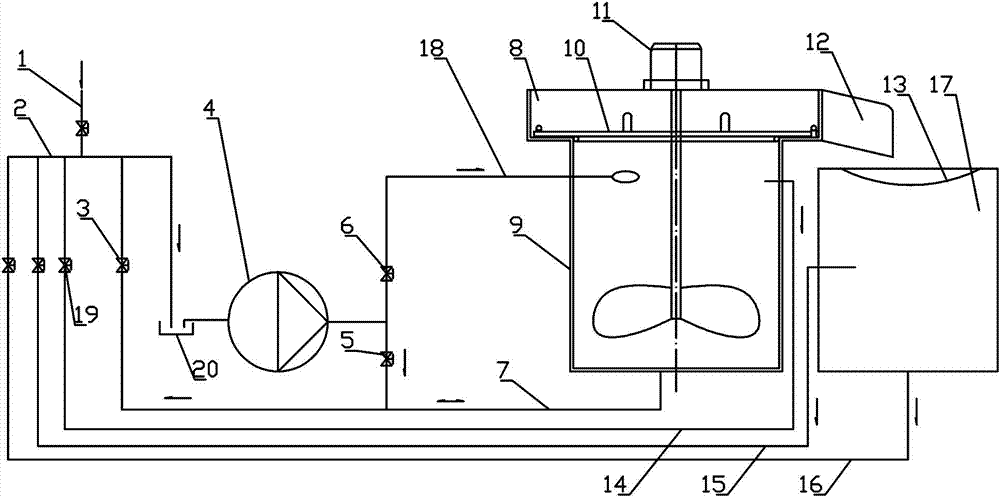
[0021] Such as figure 1 Among them, a bottle stopper cleaning machine includes a cleaning tank 9, the output port of the pump 4 communicates with the side wall of the upper part of the cleaning tank 9 near the opening through the cleaning pipe 18, and the input port of the pump 4 communicates with the cleaning tank bottom pipe 7 through the cleaning tank 9. Tank 9 is connected.
[0022] In an optimized solution, the cleaning pipe 18 communicates with the inner wall of the cleaning tank 9 in a tangential manner. With this structure, the liquid enters the cleaning tank 9 along the tangent direction of the inner wall of the cleaning tank 9, thereby pushing the liquid in the cleaning tank 9 to form a vortex, and driving the bottle stopper to rotate and roll.
[0023] With the above structure, the cleaning pipe 18 and the cleaning tank bottom pipe 7 form a liquid flow circulation through the pump 4, thereby cleaning the bottle stopper.
Embodiment 2
[0025] On the basis of Example 1, such as figure 1 Among them, a cleaning tank overflow pipe 14 is also provided, and one end of the cleaning tank overflow pipe 14 communicates with the side wall of the upper part of the cleaning tank 9 near the opening of the cleaning tank 9, and the other end communicates with the input port of the pump 4 through the fourth valve 19 , the cleaning tank bottom pipe 7 is also communicated with the output port of the pump 4 through the second valve 5;
[0026] The cleaning pipe 18 is also provided with a third valve 6 .
[0027] With this structure, two kinds of circulation are formed, one is the circulation formed in embodiment 1, that is, the liquid in the cleaning pipe 18 enters the cleaning tank 9 tangentially along the side wall of the cleaning tank 9 under the action of the pump 4, The bottle stopper and the liquid in it are formed to rotate; then the liquid is discharged from the cleaning tank bottom pipe 7, and the excess liquid is dis...
Embodiment 3
[0029] On the basis of Example 2, such as figure 1 Among them, a cleaning tank overflow portion 8 is also provided above the cleaning tank 9, a detachable gland net 10 is provided at the bottom of the cleaning tank overflow portion 8, and an overflow is provided on one side of the cleaning tank overflow portion 8. slot 12;
[0030] An overflow tank 17 is arranged below the overflow tank 12 , and an overflow screen 13 is arranged on the top of the overflow tank 17 , and the overflow tank 17 communicates with the input port of the pump 4 through the overflow tank overflow pipe 15 .
[0031] The overflow tank 17 is also communicated with the input port of the pump 4 through the overflow tank overflow pipe 15 .
[0032] The gland net 10 is a stainless steel wire mesh, the outer ring is connected with the bottom of the overflow part 8 of the cleaning tank through a stainless steel rod, and the mesh of the stainless steel wire mesh is smaller than the diameter of the circumscribed ...
PUM
 Abstract
Description
Claims
Application Information
 - R&D Engineer
- R&D Manager
- IP Professional
- Industry Leading Data Capabilities
- Powerful AI technology
- Patent DNA Extraction
Browse by: Latest US Patents, China's latest patents, Technical Efficacy Thesaurus, Application Domain, Technology Topic.
© 2024 PatSnap. All rights reserved.Legal|Privacy policy|Modern Slavery Act Transparency Statement|Sitemap