Vehicle bumper structure

A technology for bumpers and vehicles, applied in the directions of bumpers, superstructures, vehicle parts, etc., can solve problems such as strengthening the side rigidity of helpless bumpers, and achieve the effect of improving appearance

Active Publication Date: 2015-05-06
HONDA MOTOR CO LTD
View PDF5 Cites 0 Cited by
  • Summary
  • Abstract
  • Description
  • Claims
  • Application Information

AI Technical Summary

Problems solved by technology

However, although the conventional bumper side part has a closing plate inside, since the closing plate is formed in a flat plate shape, it hardly contributes to strengthening the rigidity of the bumper side part.

Method used


Image

  • Vehicle bumper structure
  • Vehicle bumper structure
  • Vehicle bumper structure

Examples


Embodiment Construction

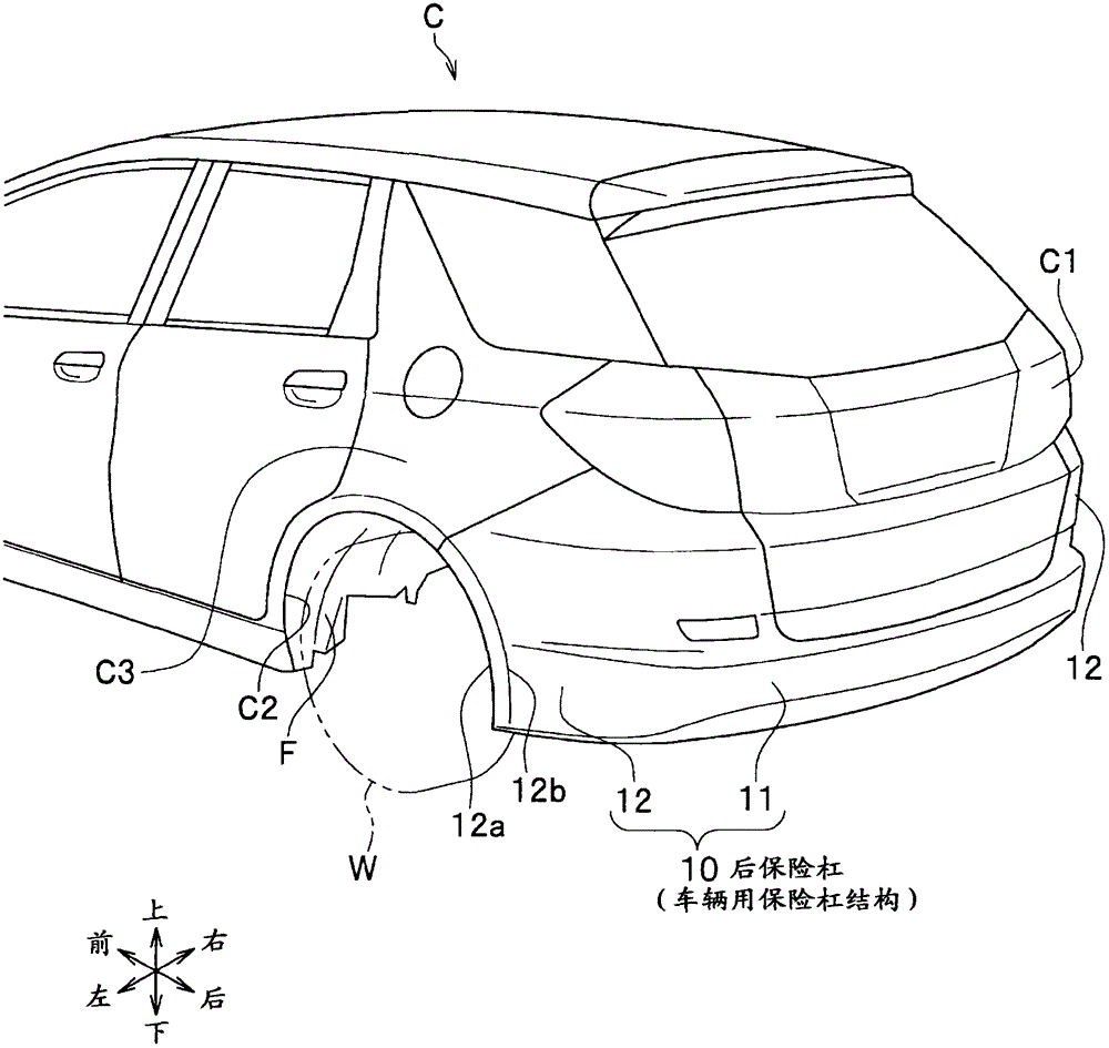
[0047] refer to Figure 1 to Figure 7 Embodiments of the present invention will be described in detail. In this embodiment, a case where the present invention is applied to a rear bumper of an automobile C which is a vehicle will be described as an example. In the description, the same reference numerals are assigned to the same elements, and repeated descriptions are omitted. In addition, when describing a direction, it demonstrates based on the front, rear, left, right, up and down seen from the driver of a vehicle.

[0048] Such as figure 1 As shown, an automobile C has a rear bumper 10 serving as a vehicle bumper structure at its rear end C1 and a wheel house C2 for accommodating a wheel W. As shown in FIG. A fender constituting member F constituting a fender covering the upper half of the wheel W is attached to the inside of the wheel house C2. The fender constituting member F will be described later.

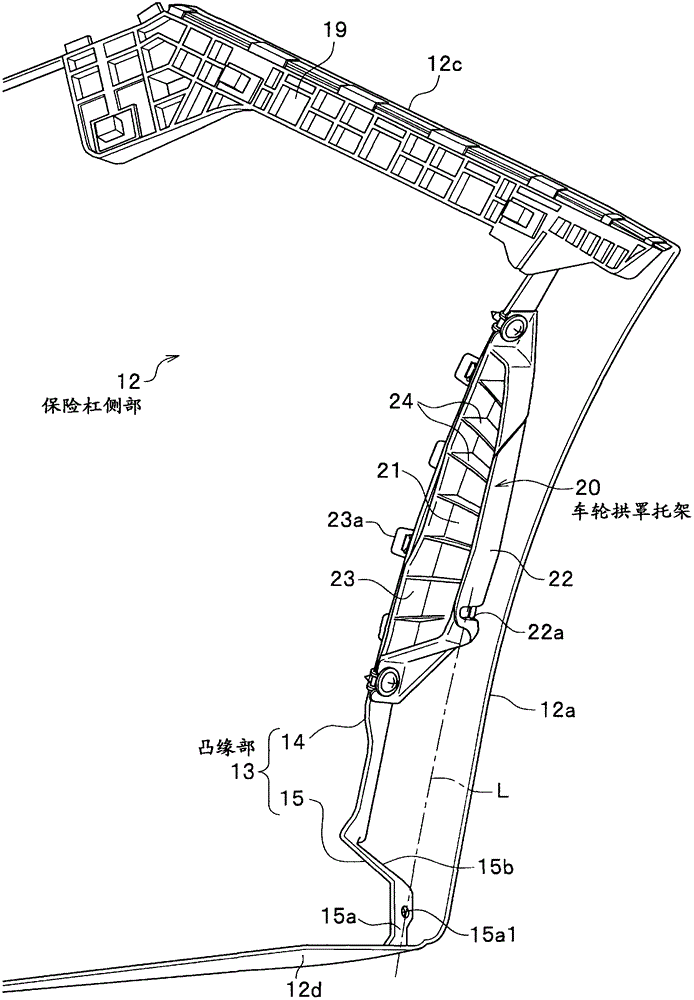
[0049]The rear bumper 10 mainly includes a bumper central portio...


PUM


Abstract

A rear bumper includes a bumper central part configured to cover a rear end portion of a vehicle, a pair of bumper side parts configured to extend from both ends of the bumper central part toward respective wheel housings, a wheel arch portion disposed at an end of each of the bumper side parts, a flange formed integrally with an inner surface of each of the bumper side parts, and a wheel arch bracket disposed on the flange and configured to support fender components. The wheel arch bracket includes a component supporting portion configured to support the fender components, a flange mount portion disposed opposite to the component supporting portion and attached to the flange, and a plurality of vertical walls configured to extend from the component supporting portion toward the flange mount portion.

Description

technical field [0001] The present invention relates to a vehicle bumper structure. Background technique [0002] Conventionally, for example, there is known a bumper structure for a vehicle in which the rear end portion of the vehicle extends in the left-right direction, and the left and right end portions extend forward to the wheel arch to form a substantially U-shaped plan view. For example, in Patent Document 1, on the inner surface of the rear bumper side member (bumper side portion) facing the wheel arch, a flange portion for attaching a fender component such as a wheel house is provided approximately vertically. [0003] In addition, a closing plate covering the boundary portion between the rear fender and the bumper side from the inside is attached to the flange portion to prevent splashing of muddy water and the like splashed in the wheel arch from the boundary portion. Partial oozing. [0004] Patent Document 1: Patent No. 2505898 [0005] In the conventional s...

Claims


Application Information

Patent Timeline
Patent Type & Authority Patents(China)
IPC IPC(8): B60R19/24B62D25/16
CPCB60R19/24B60R2019/002B60R2019/247
Inventor 广濑善隆
Owner HONDA MOTOR CO LTD
Why Eureka
Try Eureka