
Control system and method for concrete machine

A concrete machinery and control system technology, applied in the direction of mechanical equipment, fluid pressure actuation system components, building materials processing, etc., can solve the problems of high fuel consumption, unfavorable energy saving, slow action, etc., to reduce the driving speed, reduce energy consumption, etc. consumption effect

Active Publication Date: 2013-04-10
河北雷萨重型工程机械有限责任公司
View PDF3 Cites 8 Cited by
  • Summary
  • Abstract
  • Description
  • Claims
  • Application Information

AI Technical Summary

Problems solved by technology

However, for the engine, the corresponding fuel consumption under high-speed conditions is relatively high, which is not conducive to energy saving; at the same time, the limitation of the displacement of the boom pump itself leads to a relatively limited output flow of the boom pump, which will make the multi-section boom During linkage (simultaneous action), the action is slow, which affects the working efficiency

Method used


Image

  • Control system and method for concrete machine
  • Control system and method for concrete machine
  • Control system and method for concrete machine

Examples


Embodiment Construction

[0039] The specific implementation manners of the present invention will be further described in detail below in conjunction with the accompanying drawings and embodiments. The following examples are used to illustrate the present invention, but are not intended to limit the scope of the present invention.

[0040] The key point of this application is: to switch the oil supply from the main oil pump to the pumping system or the hydraulic system of the boom by controlling the reversing valve. Or provide hydraulic power to the boom hydraulic system at the same time as the boom pump. By using the characteristics of the large displacement of the main oil pump, the driving speed of the driving device can be greatly reduced to achieve energy saving; The relationship between the speed can meet the demand of any flow in the hydraulic system of the boom, and realize oil supply on demand.

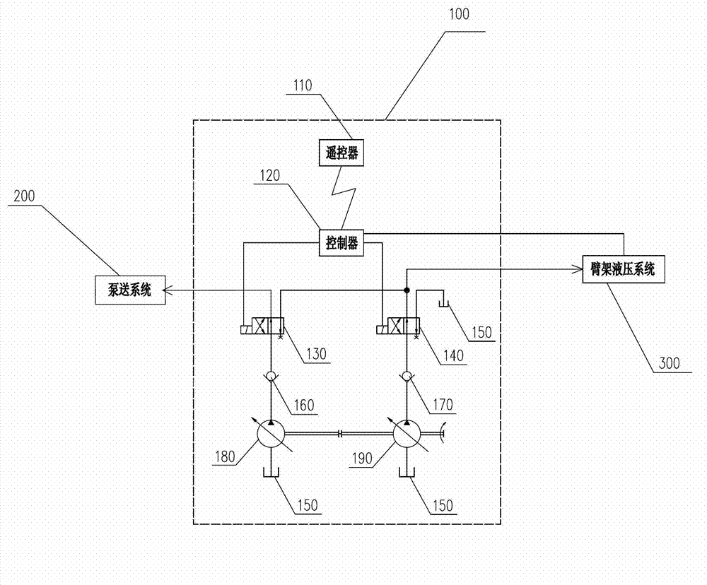
[0041] figure 1 It is a schematic diagram of the hydraulic oil flow of the control system when ...


PUM


Abstract

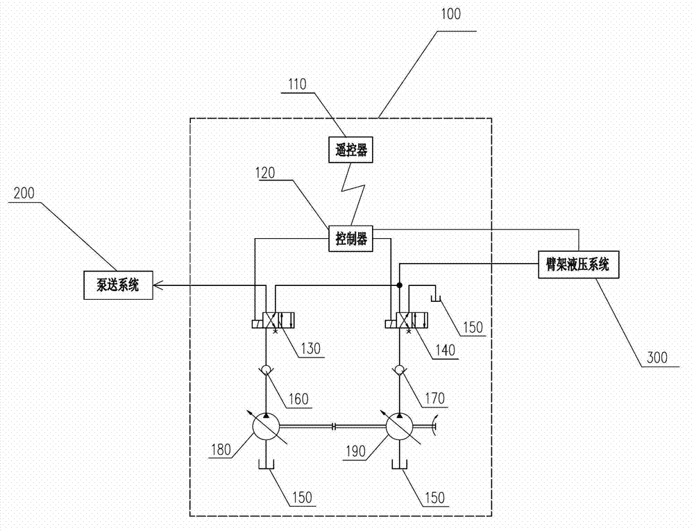
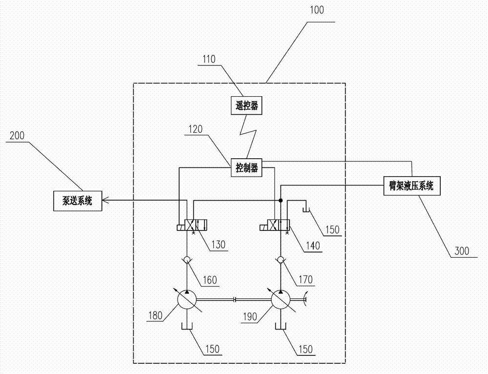
The invention discloses a control system and a control method for a concrete machine, and the system and the method relate to the technical field of mechanical equipment. According to the control system, the input end of a main oil pump is communicated with an oil tank, and the output end of the main oil pump is communicated with the input end of a first reversing valve; the output end of the first reversing valve is selectively communicated with a pumping system or a jib hydraulic system; the input end of a jib pump is communicated with the oil tank, and the output end of the jib pump is communicated with the input end of a second reversing valve; and the output end of the second reversing valve is selectively communicated with the jib hydraulic system or the oil tank. According to the control system and the control method for the concrete machine, because the reversing valves are arranged on an output pipeline of the main oil pump, the main oil pump is enabled to supply oil to the jib hydraulic system solely or together with the jib pump when the jib hydraulic system acts solely, so that the characteristic of large displacement of the main oil pump is fully utilized, the driving rotating speed of a driving device can be significantly reduced, and the energy consumption is reduced.

Description

technical field [0001] The invention relates to the technical field of mechanical equipment, in particular to a control system and method for concrete machinery. Background technique [0002] In the prior art, the pump set of a concrete machine with a boom (such as a concrete pump truck) usually includes a main oil pump and a boom pump. Among them, the main oil pump supplies oil to the pumping system and drives the pumping system to output concrete; the boom pump supplies oil to the boom system and drives the boom and outriggers to move. The pumping system and the boom system generally work independently without interfering with each other. [0003] In the actual construction process, due to the small displacement of the boom pump itself, the engine speed is generally set higher during the movement of the boom to ensure sufficient flow output to meet the movement speed of the boom. However, for the engine, the corresponding fuel consumption under high-speed conditions is r...

Claims


Application Information

Patent Timeline
Patent Type & Authority Applications(China)
IPC IPC(8): E04G21/04F15B21/08
Inventor 刘明清张华李勋文庞浩
Owner 河北雷萨重型工程机械有限责任公司
Learn More