Fan linkage pitch system

A pitch system and linkage technology, applied in the control of wind turbines, machines/engines, wind turbines, etc., can solve the problems of heavier weight of the nose part, complicated control system, short fan life, etc., to extend the operating life, guarantee The effect of safe operation and improved power generation

Active Publication Date: 2015-04-01
NINGBO GINLONG TECH
View PDF5 Cites 2 Cited by
  • Summary
  • Abstract
  • Description
  • Claims
  • Application Information

AI Technical Summary

Problems solved by technology

With this structure, several pitch drive systems are installed in the hub of the nose, which increases the volume of the hub of the nose, increases the weight of the nose, increases the moment of inertia of the impeller, complicates the control system, and increases maintenance costs.
Especially for small and medium-sized wind turbines, the mechanism of the electric pitch control system is complicated, its manufacture and installation are difficult, there are many faults, and the relative cost is relatively high
[0007] However, small wind turbines generally adopt fixed-pitch blade stall control technology and yaw control technology. Due to the influence of bad weather, there are disadvantages such as unstable power control, low power generation efficiency, poor safety, and short fan life. Even if the small and medium-sized wind turbine adopts the linkage pitch control technology, it generally adopts gear linkage, which has a complicated structure and low precision

Method used


Image

  • Fan linkage pitch system
  • Fan linkage pitch system
  • Fan linkage pitch system

Examples


Embodiment Construction

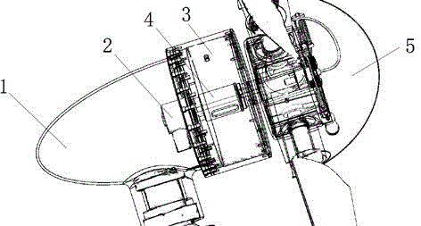
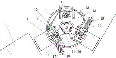
[0038] like figure 1 It is shown in the overall schematic diagram of the present invention applied to a wind power generating set. A fan is composed of a cabin 1, an electric stretching system 2, a generating set 3, a hollow generator main shaft 4 and a shroud 5. like Figures 2 to 6 As shown, a fan linkage pitch system is used for the manual and electric linkage pitch of the fan, including the blade set and the pitch system connected to the nose hub 13, and the pitch system includes manual pitch and electric pitch paddle, of which,

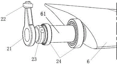
[0039] The blade group is composed of more than two blades 6 with blade root shafts 61 installed on the nose wheel hub 13 through blade shaft bearings 24), the centerlines of each blade root shafts intersect at the center line of the nose wheel hub, and the blade root shafts 61 The root part is connected with the gravity rod 21 through the profile, and each gravity rod 21 is connected with the linkage plate 10 uniformly distributed with waist h...


PUM


Abstract

The invention relates to a fan linkage pitch system, which is applied to the manual and power-driven linkage pitching for a fan. The fan linkage pitch system comprises a blade group and a pitch system which is connected with a machine head hub, and has the advantages of simple structure, low cost, excellent stability and high linkage precision. A main control system signal of the fan is used for instructing a power-driven tension system to control a blade pitching angle, and the active pitching of a blade is realized; and by the adoption of the multi-free-degree rotation of a joint bearing, the highly precise coordination of the waist hole of a linkage disc and the outer circle of the joint bearing, and the movement capability of the joint bearing in the waist hole, the high synchronization among blades of an impeller during the pitching of blades is achieved, and the problem that non-synchronization of pitching caused by non-uniform pitching force of the blades due to wind shearing, down-wind tower shadow effect and the like is solved. According to synchronized pitching and timely active pitching, the operation stability of a set is effectively improved, electricity generation is improved, the service life of the set is prolonged, and the operation safety of the set is guaranteed.

Description

technical field [0001] The patent of the present invention relates to a wind turbine linkage variable pitch system, that is, a manual and electric linkage system of a wind power generator. Background technique [0002] As a renewable, green and environmentally friendly energy, wind energy is one of the main new energy sources that my country and other countries in the world will develop at present and in the future. Due to the special working conditions such as wind speed, wind direction instability and storm in nature, it is necessary to control the fan. In order to improve the utilization rate of wind energy and protect the fan under special working conditions. [0003] All components of the pitch system of the wind turbine (hereinafter referred to as the fan) are installed on the hub. During normal operation of the fan, all parts rotate with the hub at a certain speed. The pitch system controls the speed of the wind rotor by controlling the angle of the blades, thereby...

Claims


Application Information

Patent Timeline
Patent Type & Authority Patents(China)
IPC IPC(8): F03D7/04F03D1/06
CPCY02E10/723Y02E10/721Y02E10/72
Inventor 王一鸣张天赐
Owner NINGBO GINLONG TECH
Why Eureka
Try Eureka