Fixing device and detection system

A technology for fixing devices and fixing structures, which is applied to lighting devices, lighting auxiliary devices, components of lighting devices, etc., can solve the problems of labor-consuming, time and cost, high product cost, waste of resources, etc., and shorten the work cycle. , avoid long development cycle, save product cost effect

Inactive Publication Date: 2013-04-10
BOE TECH GRP CO LTD +1
View PDF3 Cites 16 Cited by
  • Summary
  • Abstract
  • Description
  • Claims
  • Application Information

AI Technical Summary

Problems solved by technology

However, if the individual components of the backlight module are to be tested, it still needs to be assembled into the entire backlight module, and the assembly consumes a lot of manpower, time and cost, which in turn causes problems such as long development cycle, waste of resources, and high product cost.

Method used


Image

  • Fixing device and detection system
  • Fixing device and detection system
  • Fixing device and detection system

Examples


Embodiment Construction

[0033] The following will clearly and completely describe the technical solutions in the embodiments of the present invention with reference to the accompanying drawings in the embodiments of the present invention. Obviously, the described embodiments are only some, not all, embodiments of the present invention.

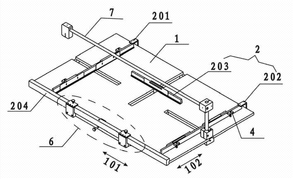
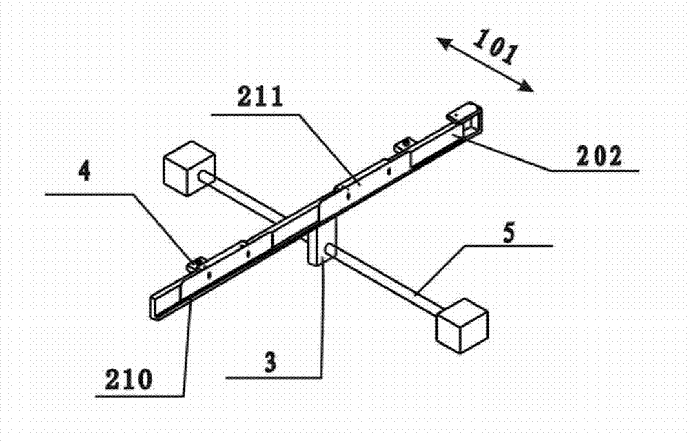
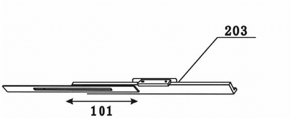
[0034] The embodiment of the present invention provides a fixing device, such as figure 1 , figure 2 As shown, it includes: a support platform 1; at least two position-limiting side walls 2, arranged on the support platform 1, for limiting the position of the edge of the object carried by the support platform, wherein at least one position-limiting side wall It is a movable limit side wall; the sliding part 3 is connected with the movable limit side wall and is used to move along the vertical direction of the movable limit side wall; the fixed part 4 is arranged on the movable limit side wall The limit side wall or the sliding part is used to fix the movable limit ...


PUM


Abstract

The invention provides a fixing device and a detection system, relating to the field of detection of a display device and solving the problem that the detection can only be performed by connecting and assembling all components of a backlight module into a model in the prior art. The fixing device comprises a supporting platform, at least two limiting side walls, a sliding part and a fixing part, wherein the limiting side walls are arranged on the supporting platform for limiting the position of the edge of an object carried by the supporting platform; at least one limiting side wall is a movable limiting side wall; the sliding part is connected with the movable limiting side wall for moving along the vertical direction of the movable limiting side wall; and the fixing part is arranged on the movable limiting side wall or the sliding part for fixing the movable limiting side wall at a certain position. The fixing device and the detection system are suitable for design and manufacturing of a detection part.

Description

technical field [0001] The invention relates to the field of display device detection, in particular to a fixing device and a detection system. Background technique [0002] In most of the existing liquid crystal displays, the liquid crystal panel itself does not emit light. In order to realize the display function, it needs the assistance of an external backlight source. Most of the existing external backlights are edge-lit backlight modules, including: a light source, a reflector, a light guide plate, a condensing prism, and a diffuser, whose main function is to convert scattered light into planar light. The light source is placed on the side of the backlight module, and the white light generated by the light source enters from the entrance of the light guide plate, and is diffusely reflected by the reflector under the light guide plate, propagates to the upper surface of the light guide plate along multiple paths, and then emits as flat light , and then pass through a li...

Claims


Application Information

Patent Timeline
Patent Type & Authority Applications(China)
IPC IPC(8): F21V21/00
Inventor 徐高军韩锐张慎平刘怿云
Owner BOE TECH GRP CO LTD
Why Eureka
Try Eureka