Method for measuring heat consuming user heating load of vertical single tube cocurrent type system and heating metering distributing system of vertical single tube cocurrent type system

A technology for heat supply and heat users, which is applied in the field of heat metering and distribution systems, can solve the problems of difficult heat metering transformation of building vertical single-pipe downstream systems, and achieve the effect of simple transformation, less disturbance to residents, and low transformation cost

Active Publication Date: 2015-06-10
HARBIN INST OF TECH
View PDF4 Cites 0 Cited by
  • Summary
  • Abstract
  • Description
  • Claims
  • Application Information

AI Technical Summary

Problems solved by technology

[0039] The purpose of the present invention is to solve the problem of difficult heat metering transformation of the vertical single-pipe downstream system in existing buildings, and provide a method for measuring the heat supplied by heat users in the vertical single-pipe downstream system and its heat metering and distribution system

Method used


Image

  • Method for measuring heat consuming user heating load of vertical single tube cocurrent type system and heating metering distributing system of vertical single tube cocurrent type system
  • Method for measuring heat consuming user heating load of vertical single tube cocurrent type system and heating metering distributing system of vertical single tube cocurrent type system
  • Method for measuring heat consuming user heating load of vertical single tube cocurrent type system and heating metering distributing system of vertical single tube cocurrent type system

Examples


specific Embodiment approach 1

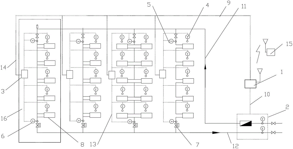
[0064] Specific implementation mode one: see Figure 5 To illustrate this embodiment, the specific calculation process of the method for measuring the heat supplied to users in a vertical single-pipe downstream system described in this embodiment is:

[0065] Step 1, collect the total heat supply of the building through the heat meter;

[0066] Step 2, collect the actual room temperature of each user in the building through the room temperature sensor installed in each household;

[0067] Step 3, collect the water supply temperature of the standpipe through the water supply temperature sensor arranged at the uppermost end of each standpipe of the heating system;

[0068] Step 4: Collect the return water temperature of the standpipe through the return water temperature sensor at the bottom of each standpipe in the heating system;

[0069] Step 5, by adjusting the opening of the flow controller arranged on each standpipe, the heating system is adjusted to balance, and the flow...

specific Embodiment approach 2

[0077] Embodiment 2: The difference between this embodiment and the method for measuring the heat supply of heat users in the vertical single-pipe downstream system described in Embodiment 1 is that the calculation of the heat supply of each standpipe in the step 8 The method is:

[0078] For a building with m risers, where m is a natural number greater than 1, the characteristic coefficient a of riser i calculated according to step 7 i The value is calculated according to the formula (5), i is the serial number of the riser, and i is any natural number less than or equal to m,

[0079] Q ij =a i x ij (5)

[0080] In the formula:

[0081] Q ij Indicates the heat supply of standpipe i under working condition j, the unit is KJ;

[0082] a i Indicates the characteristic coefficient a value of riser i;

[0083] x ij Indicates the unit heat dissipation of the radiator on the riser i under the j working condition, which is determined according to the temperature d...

specific Embodiment approach 3

[0085] Embodiment 3: The difference between this embodiment and the method for measuring the heat supply of heat users in the vertical single-pipe downstream system described in Embodiment 1 is that the method for calculating the flow rate of each standpipe in the above step 9 is as follows: :

[0086] According to the water supply temperature, return water temperature and heat supply of standpipe i obtained in step 3, step 4 and step 8 in working condition j, the flow rate of standpipe is calculated according to formula (6),

[0087] G ij = Q ij c ( t ijg - t ijh ) - - - ( 6 )

[0088] In ...


PUM


Abstract

The invention provides a method for measuring heat consuming user heating load of a vertical single tube cocurrent type system and a heating metering distributing system of the vertical single tube cocurrent type system, and relates to a heating metering distributing system. The method for measuring heat consuming user heating load of the vertical single tube cocurrent type system and the heating metering distributing system of the vertical single tube cocurrent type system solve the problem that an existing vertical single tube cocurrent type system in buildings is difficult to remould. A flow controller locking balanced flow is placed on each stand pipe of each apartment, each stand pipe is provided with a water supply temperature sensor and a water returning temperature sensor, each user family is provided with a room temperature sensor, and a calorimeter is placed in a total building heating entry well. Heat dissipating capacity of each stand pipe and radiators at each floor and equivalent heat consumed by each heat consuming user are measured according to the measured water supply temperature and water returning temperature of each stand pipe and the measured room temperature in each user. The method for measuring the heat consuming user heating load of the vertical single tube cocurrent type system and the heating metering distributing system of the vertical single tube cocurrent type system are suitable for heat metering reformations of a vertical single tube cocurrent type system connected on the single side, a vertical single tube cocurrent type system connected on two sides without a crossing tube and a vertical single tube cocurrent type system connected on two sides with a crossing tube and radiators at the same user.

Description

technical field [0001] The invention relates to a heat metering and distribution system, in particular to a method for measuring the heat supplied by a heat user in a vertical single-pipe downstream system and a heat metering and distribution system thereof. Background technique [0002] my country is a big country in construction. By the end of 2005, the construction area of ​​urban housing in the country reached 16.488 billion m 2 , of which the urban civil construction area is 14.744 billion m 2 Residential construction area 10.769 billion m 2 , the public building area is 3.975 billion m 2 . In order to maintain the indoor temperature, a large amount of energy is consumed every year. In order to reduce building energy consumption, my country has promulgated and implemented energy-saving design standards for residential buildings since the 1980s. my country's building energy conservation begins with the design of new buildings in northern central heating areas. In s...

Claims


Application Information

Patent Timeline
Patent Type & Authority Patents(China)
IPC IPC(8): G01K17/06
Inventor 方修睦姜永成李庆宇孙杰
Owner HARBIN INST OF TECH
Why Eureka
Try Eureka