
Door lock structure of push-pull type ring main unit

A technology of door lock structure and ring network cabinet, which is applied to padlocks, building locks, building structures, etc., can solve the problems of operation interference, affecting unlocking and locking operations, and affecting work efficiency, so as to achieve convenient and labor-saving operation , improve efficacy, and facilitate operation

Pending Publication Date: 2020-02-11
JIANGSU ELECTRIC POWER CO +1
View PDF1 Cites 7 Cited by
  • Summary
  • Abstract
  • Description
  • Claims
  • Application Information

AI Technical Summary

Problems solved by technology

At present, compared with the traditional padlock structure, this kind of door lock structure has greatly improved safety, reliability and anti-theft performance. However, the problem found in the actual use process is: because the ring network cabinet is generally located in the outdoor green belt Or on the side of the road, it is easy to be rusted and jammed. At present, the door lock structure used in the ring network cabinet adopts the structure of separating and closing the sky and earth pole through the rotating handle. When the parts and / or the heaven and earth rod are jammed or deformed, it is very laborious to turn the rotary handle, and it is very difficult to lock it, which seriously affects the work efficiency, and even the connection of the rotating handle or the connection between the connecting part and the sky and earth rod may be caused by the operation and maintenance personnel's vigorous rotation. In addition, in the existing structure, the sky-earth rod is directly connected with the connecting piece, so that the alignment between the sky-earth rod and the insertion hole on the cabinet body is prone to inaccurate alignment and it is difficult to lock; in addition, the box cover is lifted upwards. The structure will interfere with the operation during use and affect the unlocking and locking operations
[0003] With the advancement of technology, the current ring network cabinet equipped with intelligent door locks has also been applied. For example, the Chinese patent document with the publication number CN204189215U proposes a ring network cabinet lock with intelligent identification function. By identifying whether the key is authorized To realize the opening and closing of the internal structure of the lock, this type of smart lock has a stronger anti-theft function than the commonly used padlock, but the cost of large-scale transformation of the existing ring network cabinet door locks into smart locks is relatively high, and it is not economical. In the actual use of smart locks, there are also problems such as the power of the smart lock key is not easy to control, and there are often problems such as the operation and maintenance personnel cannot open the door when the key is out of power when they arrive at the scene.

Method used


Image

  • Door lock structure of push-pull type ring main unit
  • Door lock structure of push-pull type ring main unit
  • Door lock structure of push-pull type ring main unit

Examples


Embodiment 1)

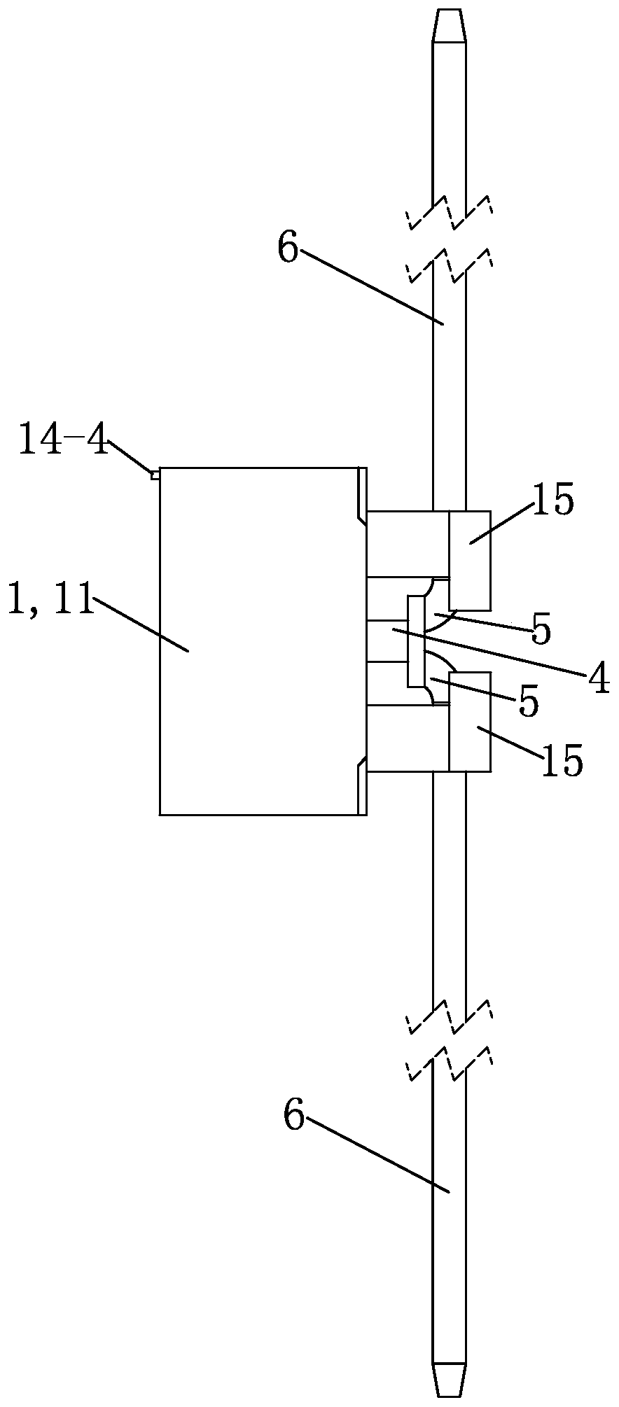
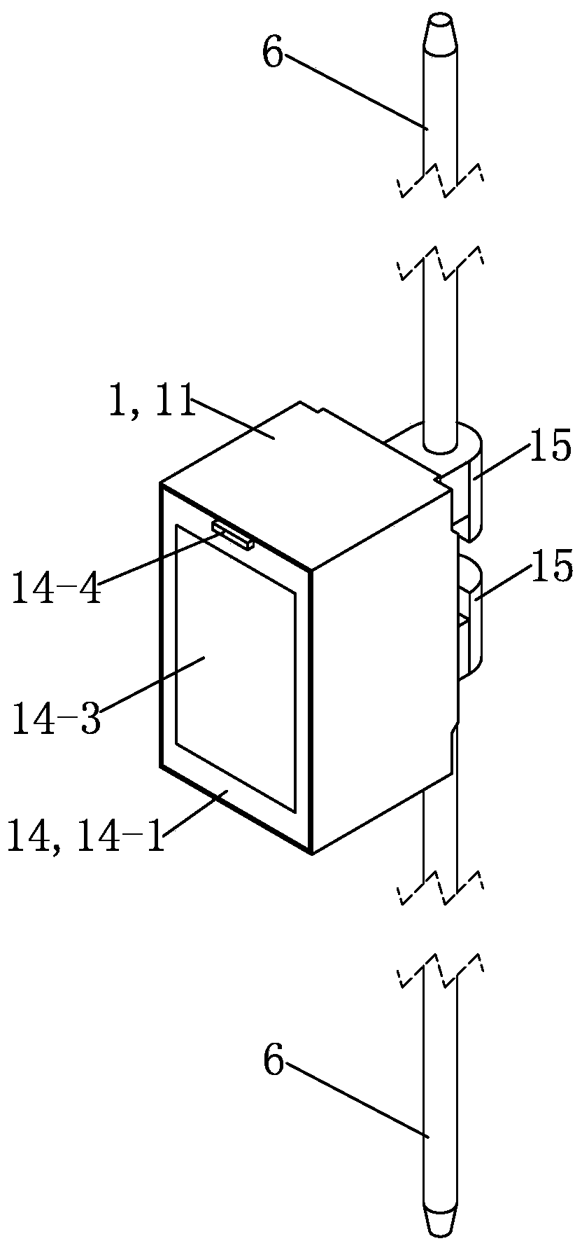
[0034] See Figure 1 to Figure 6 , The push-pull ring network cabinet door lock structure of the present embodiment mainly consists of a lock body 1, a push-pull handle 2, an inner connector 3, an outer connector 4, a steel wire pipe 5, a lock bar 6 and a padlock 7.

[0035] see Figure 10 and Figure 5 , lock body 1 is installed base as door lock structure, and lock body 1 mainly is made up of box body 11, handle support member 12, padlock dead bolt 13, box cover 14 and lock bar installation stopper 15.

[0036] The box body 11 is a square box-shaped piece with an open front, and each of the four corners of the rear plate of the box body 11 is provided with a mounting hole 11-1, which is matched with the four mounting holes 11-1 by screws or bolts during use. The lock body 1 will be fixed on the cabinet door of the ring network cabinet; the middle of the back plate of the box body 11 is provided with a through hole through the front and back as a connection through hole (no...


PUM


Abstract

The invention provides a door lock structure of a push-pull type ring main unit. The door lock structure comprises two lock rods which are matched with insertion holes in a ring main unit body in useand are arranged up and down. The door lock structure is structurally characterized by further comprising a lock body which is fixedly arranged on a door of the ring main unit and serves as a mountingbase of the door lock structure, a push-pull driving mechanism which is arranged on the lock body and is used for driving the two lock rods to vertically move up and down through forward and backwardpush-pull movement to realize locking and unlocking of the door of the ring main unit, and a padlock which is used for locking the lock body; the push-pull driving mechanism comprises a push-pull handle, an inner connecting piece, an outer connecting piece and two steel wire pipes; the push-pull handle is sleeved with the inner connecting piece and can rotate relative to the inner connecting piece, the inner connecting piece is in threaded connection with the outer connecting piece, and one ends of the two steel wire pipes are fixedly connected with the outer connecting piece; and the other ends of the two steel wire pipes are fixedly connected with the ends, close to the lock body, of the two lock rods correspondingly. The door lock structure is relatively simple in structure, relativelylow in cost and capable of realizing locking and unlocking conveniently in a labor-saving mode in use.

Description

technical field [0001] The invention relates to the field of matching devices of ring network cabinets in distribution networks, in particular to a push-pull ring network cabinet door lock structure. Background technique [0002] With the continuous development of society, especially cities, the number of ring main units as one of the important intermediate equipment in the distribution network continues to increase. In order to ensure the normal operation and safety of the ring main unit, it is necessary to lock the ring main unit. The traditional method of locking the ring network cabinet is to install a device such as a hanging lug or a deadbolt on the door of the cabinet and then install a padlock. The environment makes it difficult to open the padlock. The padlock and its associated lugs or bolts are prone to corrosion and damage. At the same time, the exposure of the padlock can also easily lead to lock picking and theft. Therefore, the traditional locking method is ba...

Claims


Application Information

Patent Timeline
Patent Type & Authority Applications(China)
IPC IPC(8): E05C9/04E05C9/10E05C9/18E05C9/22E05B67/38E05B17/00E06B3/38E05B65/02
CPCE05C9/047E05C9/10E05C9/1833E05C9/22E05B67/383E05B17/002E06B3/38E05B65/02
Inventor 苏华陈斌彭涛奚永平
Owner JIANGSU ELECTRIC POWER CO
Learn More