Scanning projection apparatus and scanning image display

A technology of an image display device and a projection device, which is applied in the direction of using the projection device image reproducer, image communication, picture replicator, etc., to achieve the effect of simple structure and meeting safety standards

Inactive Publication Date: 2013-04-10
HITACHI MEDIA ELECTORONICS CO LTD
View PDF9 Cites 14 Cited by
  • Summary
  • Abstract
  • Description
  • Claims
  • Application Information

AI Technical Summary

Problems solved by technology

[0005] For example, as a method of achieving high brightness, there is a method of forming multiple screens by using multiple laser light sources, but in this case, it is necessary to prevent multiple beams from entering the human eye at the same time.

Method used


Image

  • Scanning projection apparatus and scanning image display
  • Scanning projection apparatus and scanning image display
  • Scanning projection apparatus and scanning image display

Examples


Embodiment 1

[0051] The first embodiment of the present invention will be described with the drawings.

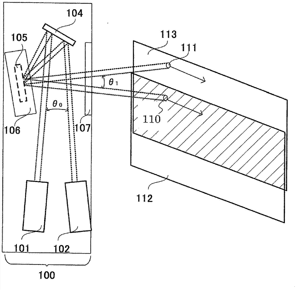
[0052] figure 1 It is an explanatory diagram of the scanning projection apparatus 100 according to the first embodiment of the present invention. The dotted line on the way indicates the beam diameter. Among them, the beam diameter is the diameter at which the light intensity of the beam becomes 1 / exp(2) relative to the light intensity on the optical axis.

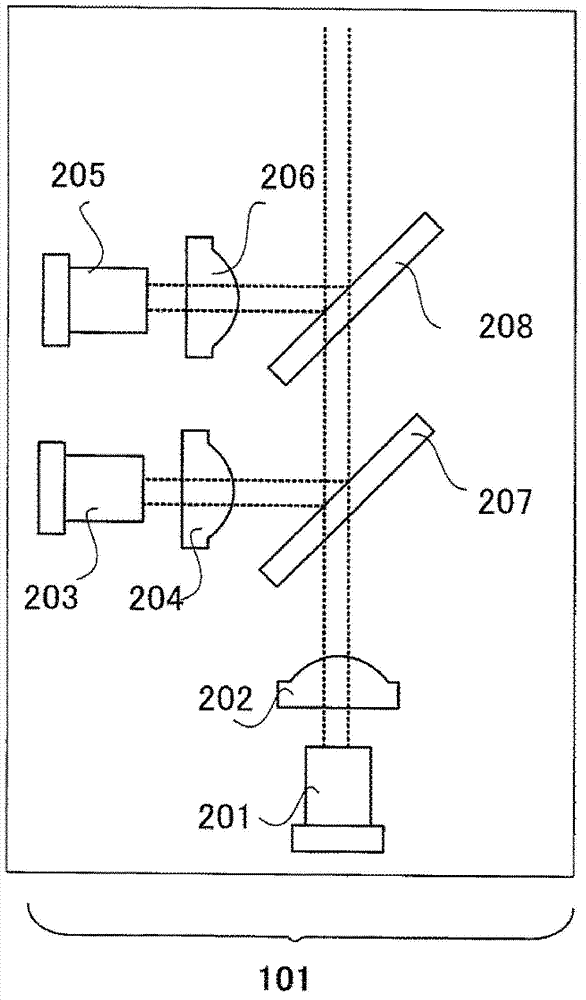
[0053] figure 2 Yes figure 1 A detailed view of the RGB light source 101 in. The RGB light source here refers to a light source obtained by combining the three primary colors required to display red (Red), green (Green), and blue (Blue) images. The dotted line in the figure represents the diameter of the beam.

[0054] The laser light source 201 is, for example, a semiconductor laser that emits a green light beam in the 520 nm band. The green light beam emitted from the laser light source 201 is converted by the collimator lens 202 in...

Embodiment 2

[0081] Next, Embodiment 2 of the present invention will be described with reference to the drawings.

[0082] Figure 4 It is an explanatory diagram of the scanning projection device 400 in the second embodiment.

[0083] The scanning projection device 400 has a light refraction element 103 added to the scanning projection device 100 in the first embodiment.

[0084] The other optical components are the same as those of the scanning projection apparatus 100, and the same reference numerals are assigned, and detailed descriptions are omitted. Two light beams of three colors synthesized by the RGB light sources 101 and 102 respectively enter the light refraction element 103. The light refraction element 103 is an element that can bend the light beams from the RGB light sources 101 and 102 to any angle using the principle of light refraction. The light refraction element 103 can make the light beams from the RGB light sources 101 and 102 at a relative angle θ 0 Shoot out.

[0085] use ...

Embodiment 3

[0104] Next, Embodiment 3 of the present invention will be described with reference to the drawings.

[0105] Picture 9 It is an explanatory diagram of the scanning projection device 500 in the third embodiment.

[0106] The scanning projection device 500 has a light combining element 108 added to the scanning projection device 100 in the first embodiment.

[0107] The other optical components are the same as those of the scanning projection apparatus 100, and the same reference numerals are assigned, and detailed descriptions are omitted. Two light beams of three colors synthesized by the RGB light sources 101 and 102 respectively enter the light synthesis element 108.

[0108] Here, use Picture 10 The details of the photosynthesis element 108 will be described. The light combining element 108 is a trapezoidal optical element, and the light beams from the RGB light sources 101 and 102 are incident approximately perpendicularly as shown in the figure. The light beams from the RGB ...


PUM


Abstract

The present invention provides a scanning projection apparatus and a scanning image display. In a light beam scanning projection apparatus coinciding a plurality of images to form one image, high luminance of the image is realized while safety standards are accorded with a simple structure. In a light beam scanning projection apparatus which scans a light beam emitted from a laser light source, an image display apparatus is configured including a plurality of light beams, a reflection mirror for reflecting the light beams to project them onto a screen or the like, and a mirror driving unit for driving the reflection mirror so that the plurality of light beams are incident on the reflection mirror with different optical axes and projected on different projection areas, thereby displaying a single image with a plurality of images. Further, by forming a single image by causing a plurality of the light beams to have predetermined relative angles thereamong so as to make a plurality of images overlap on each other with slight shifts, a scanning projection apparatus is provided with which the luminance of the image is improved while conforming to safety standards.

Description

Technical field [0001] The present invention relates to a scanning projection device and a scanning image display device, and more particularly to an optical device that projects and displays an image on, for example, a predetermined projection screen by scanning a light beam in two dimensions with a predetermined beam deflecting unit. Background technique [0002] In recent years, various scanning projection devices or scanning image display devices have been proposed, which project a light beam emitted from a predetermined light source onto a predetermined screen, and use a predetermined deflection unit to deflect the light beam two-dimensionally to achieve The light beam is scanned in two dimensions on the screen, and a two-dimensional image is projected and displayed on the screen through its visual persistence effect. [0003] As a specific example of such a scanning image display device, for example, there is an example disclosed in Patent Document 1 below. [0004] In such a ...

Claims


Application Information

Patent Timeline
Patent Type & Authority Applications(China)
IPC IPC(8): G02B26/10G02B26/08G02B27/10G02B1/00H04N9/31
CPCG02B26/105G02B27/1006G02B27/104G02B27/1066G02B27/141H04N9/3129
Inventor 畑木道生仲尾武司川村友人大西邦一喜田裕美
Owner HITACHI MEDIA ELECTORONICS CO LTD
Why Eureka
Try Eureka