
Illumination device and projector

一种照明装置、投影仪的技术,应用在放映装置、仪器、光学等方向,能够解决装置大型化装置整体厚度变厚等问题

Active Publication Date: 2016-12-21
SEIKO EPSON CORP
View PDF3 Cites 0 Cited by
  • Summary
  • Abstract
  • Description
  • Claims
  • Application Information

AI Technical Summary

Problems solved by technology

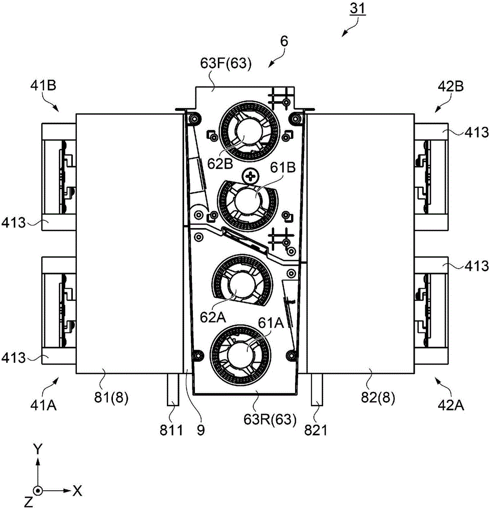
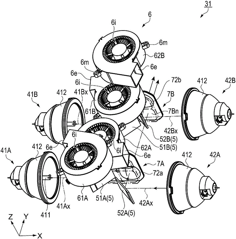
[0005] However, since the lamp unit described in Patent Document 1 has a structure in which four ventilation fans are stacked on each lamp holder, there are problems in that the size of the device increases and the thickness of the entire device becomes thicker.

Method used


Image

  • Illumination device and projector
  • Illumination device and projector
  • Illumination device and projector

Examples


Embodiment Construction

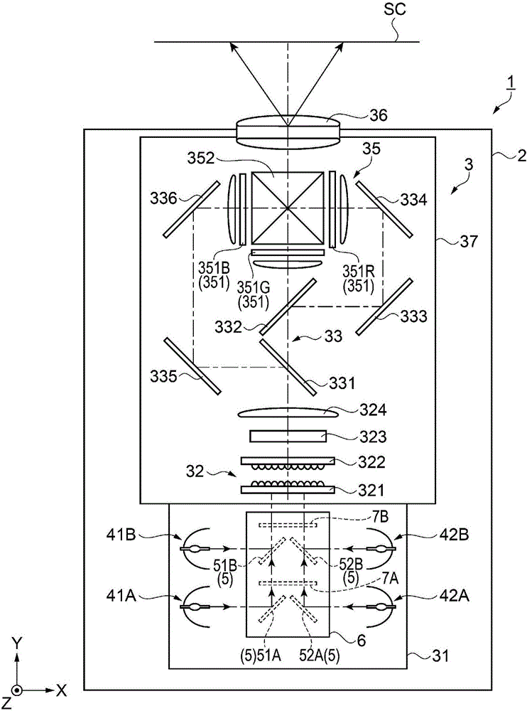
[0052] Next, a projector according to this embodiment will be described with reference to the drawings.

[0053] The projector of this embodiment modulates light emitted from a light source based on image information, and enlarges and projects the modulated light on a projection surface such as a screen. In addition, the projector according to the present embodiment is configured to be placed on a table or the like, and can assume a horizontal position in which a horizontally long image is projected on the projection plane, and can be rotated from the horizontal position when viewed from the side facing the projection plane. The portrait orientation that projects a vertically long image on the projection surface at 90°.

[0054] 〔The main structure of the projector〕

[0055] figure 1 It is a schematic diagram showing a schematic configuration of the projector 1 according to the present embodiment.

[0056] Such as figure 1 As shown, the projector 1 includes an exterior cas...


PUM


Abstract

An illumination device includes: a first light source device and a second light source device that emit light in directions opposite to each other in a first direction; a reflective portion that is disposed between the first light source device and the second light source device, and reflects the light emitted from the first light source device and the second light source device in a second direction crossing the first direction; and a cooling device that is disposed on one side of the reflective portion in a direction crossing the first direction and the second direction, and blows cooling air to the first light source device and the second light source device.

Description

technical field [0001] The invention relates to an illuminating device and a projector. Background technique [0002] Conventionally, there is known a projector that modulates light emitted from a light source based on image information, and projects the modulated light on a projection surface such as a screen. In addition, there has been proposed a device configured to include a plurality of light sources to project a brighter image and cool the light sources (for example, refer to Patent Document 1). [0003] The device (lamp unit) described in Patent Document 1 includes: a lamp fan base forming a housing structure; The base is supported to be movable, and four light source lamps are respectively mounted on the four lamp holders; a fan base, on which a blower fan is placed and supported on the lamp fan base; and a duct, The duct is arranged on the fan base, and guides the air from the blower fan toward the light-emitting part of the light source lamp. Four blower fans a...

Claims


Application Information

Patent Timeline
Patent Type & Authority Applications(China)
IPC IPC(8): G03B21/20G03B21/16
CPCG03B21/16G03B21/006G03B21/12G03B21/2013G03B21/2066G03B21/20
Inventor 泷泽孝浩佐佐木史秀堀子由季浩
Owner SEIKO EPSON CORP
Learn More