Liquid-crystal projector
a liquid crystal projector and projector technology, applied in projectors, color television details, instruments, etc., can solve the problems of less than 50% light loss in the liquid crystal panel section, no projection image with sufficient brightness can be provided, etc., to increase the luminous flux of emitted light, reduce light loss, and high light utilitization efficiency
- Summary
- Abstract
- Description
- Claims
- Application Information
AI Technical Summary
Benefits of technology
Problems solved by technology
Method used
Image
Examples
first exemplary embodiment
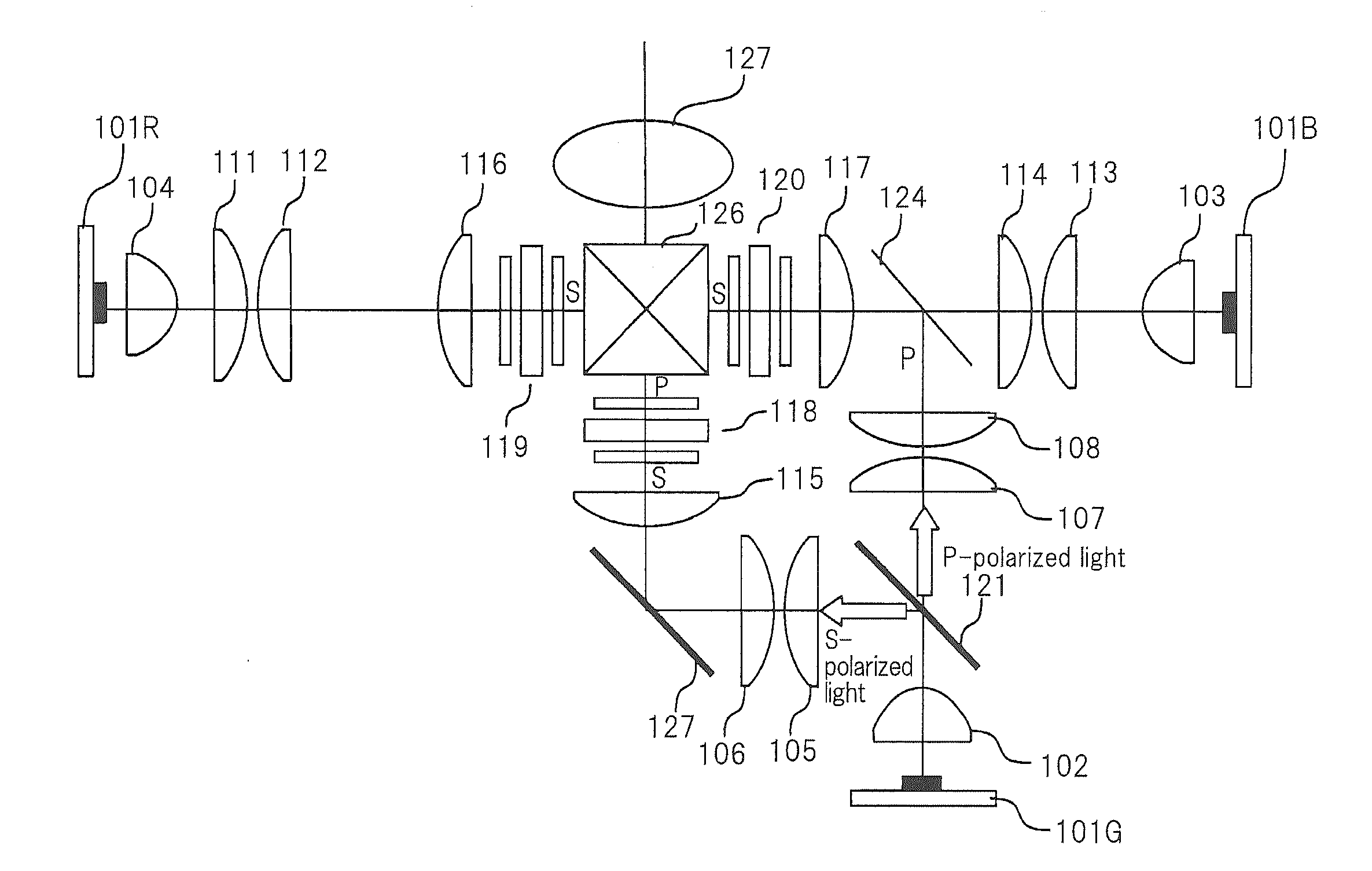
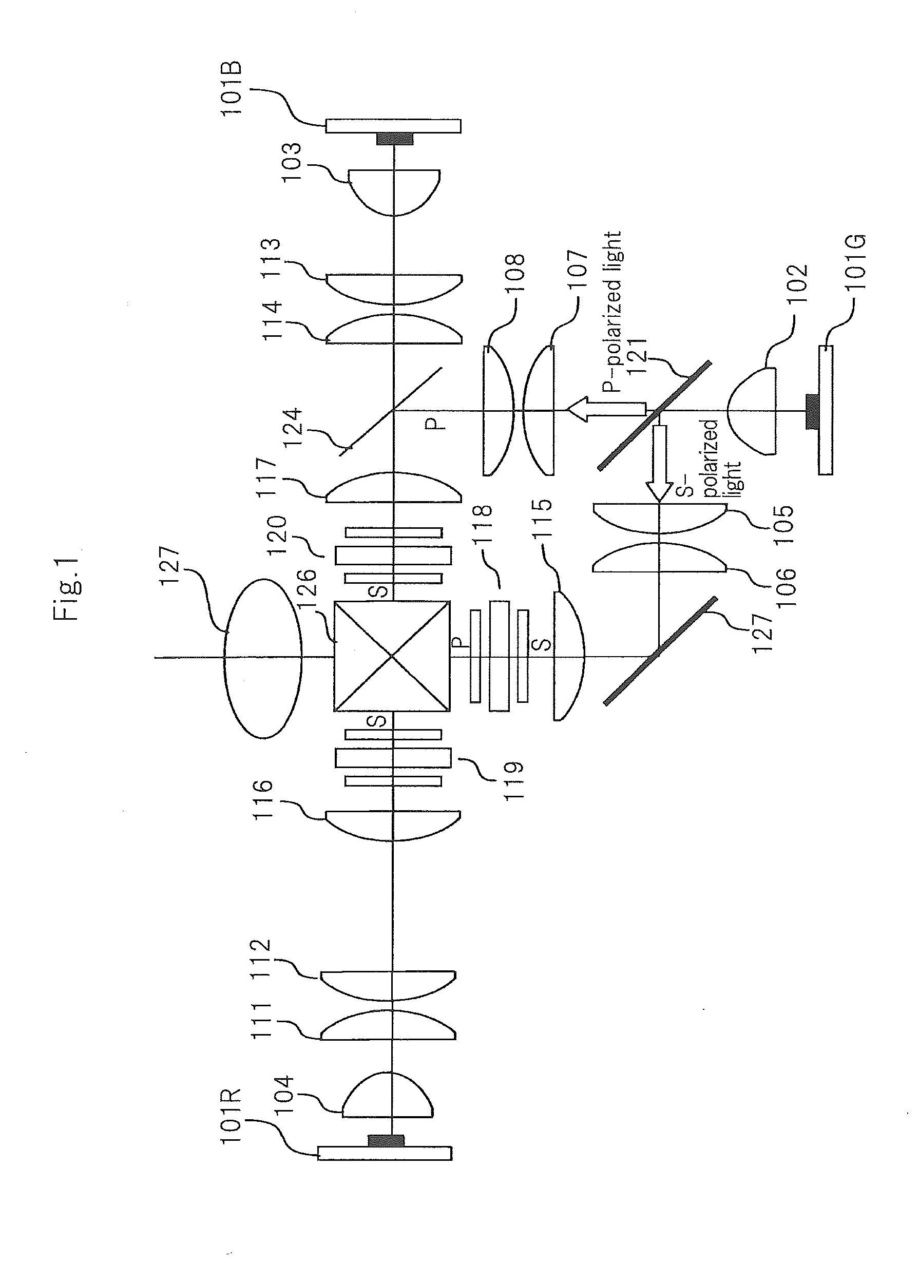
[0076]FIG. 1 is a schematic diagram illustrating a configuration of a liquid-crystal projector that is a first exemplary embodiment.
[0077]Referring to FIG. 1, the liquid-crystal projector according to the present exemplary embodiment includes three light sources: green light source 101G, red light source 101R and blue light source 101B.
[0078]Green light source 101G is a solid state light source whose peak wavelength is set in a green wavelength band, and includes, for example, an LED or a semiconductor laser whose emission color is green. Red light source 101R is a solid state light source whose peak wavelength is set in a red wavelength band, and includes, for example, an LED or a semiconductor laser whose emission color is red. Blue light source 101B is a solid state light source whose peak wavelength is set in a blue wavelength band, and includes, for example, an LED or a semiconductor laser whose emission color is blue.
[0079]However, it is known that LEDs or the like have peak w...
second exemplary embodiment
[0138]FIG. 7 is a schematic diagram illustrating a configuration of a liquid-crystal projector that is a second exemplary embodiment.
[0139]The liquid-crystal projector illustrated in FIG. 7 has a configuration that is the same as that of the first exemplary embodiment except for the addition of polarizing beam splitter 122, reflective mirror 125 and lenses 109 and 110 and provision of cross dichroic mirror 123 instead of reflective mirror 127. In FIG. 7, components that are the same as those of the first exemplary embodiment are provided with reference numerals that are the same as those of the first exemplary embodiment, and a detailed description thereof will be omitted here.
[0140]Lens 104 and polarizing beam splitter 122 are arranged in the travelling direction of red light from red light source 102. Red light from red light source 102 enters polarizing beam splitter 122 via lens 104.
[0141]Polarizing beam splitter 122 splits incident light into first linearly-polarized light and ...
PUM
 Abstract
Description
Claims
Application Information
 - R&D
- Intellectual Property
- Life Sciences
- Materials
- Tech Scout
- Unparalleled Data Quality
- Higher Quality Content
- 60% Fewer Hallucinations
Browse by: Latest US Patents, China's latest patents, Technical Efficacy Thesaurus, Application Domain, Technology Topic, Popular Technical Reports.
© 2025 PatSnap. All rights reserved.Legal|Privacy policy|Modern Slavery Act Transparency Statement|Sitemap|About US| Contact US: help@patsnap.com


