
Connecting device and connecting device assembly

A technology of board-end connectors and wire-end connectors, which is applied in the direction of connection, contact parts, protective grounding/shielding devices of connecting parts, etc., can solve problems such as unreliable grounding, increased electromagnetic leakage, and electrostatic discharge, etc., to achieve good electromagnetic Protection and grounding protection, elimination of voltage difference, good shielding effect

Inactive Publication Date: 2013-04-10
FCI ASIA PTE LTD
View PDF5 Cites 6 Cited by
  • Summary
  • Abstract
  • Description
  • Claims
  • Application Information

AI Technical Summary

Problems solved by technology

In some cases, especially in the field of communication, the receptacle connector is often placed idly on the mounting panel, at this time, the receptacle connector will increase the electromagnetic leakage due to the open end opening
Also, since there is no plug connector tightly mated with the receptacle connector to sandwich the mounting panel at this time, the receptacle connector will make loose contact with the mounting panel or even not contact at all, so there may also be a gap between the two. voltage difference, and thus also the risk of electrostatic discharge and unreliable grounding

Method used


Image

  • Connecting device and connecting device assembly
  • Connecting device and connecting device assembly
  • Connecting device and connecting device assembly

Examples


Embodiment Construction

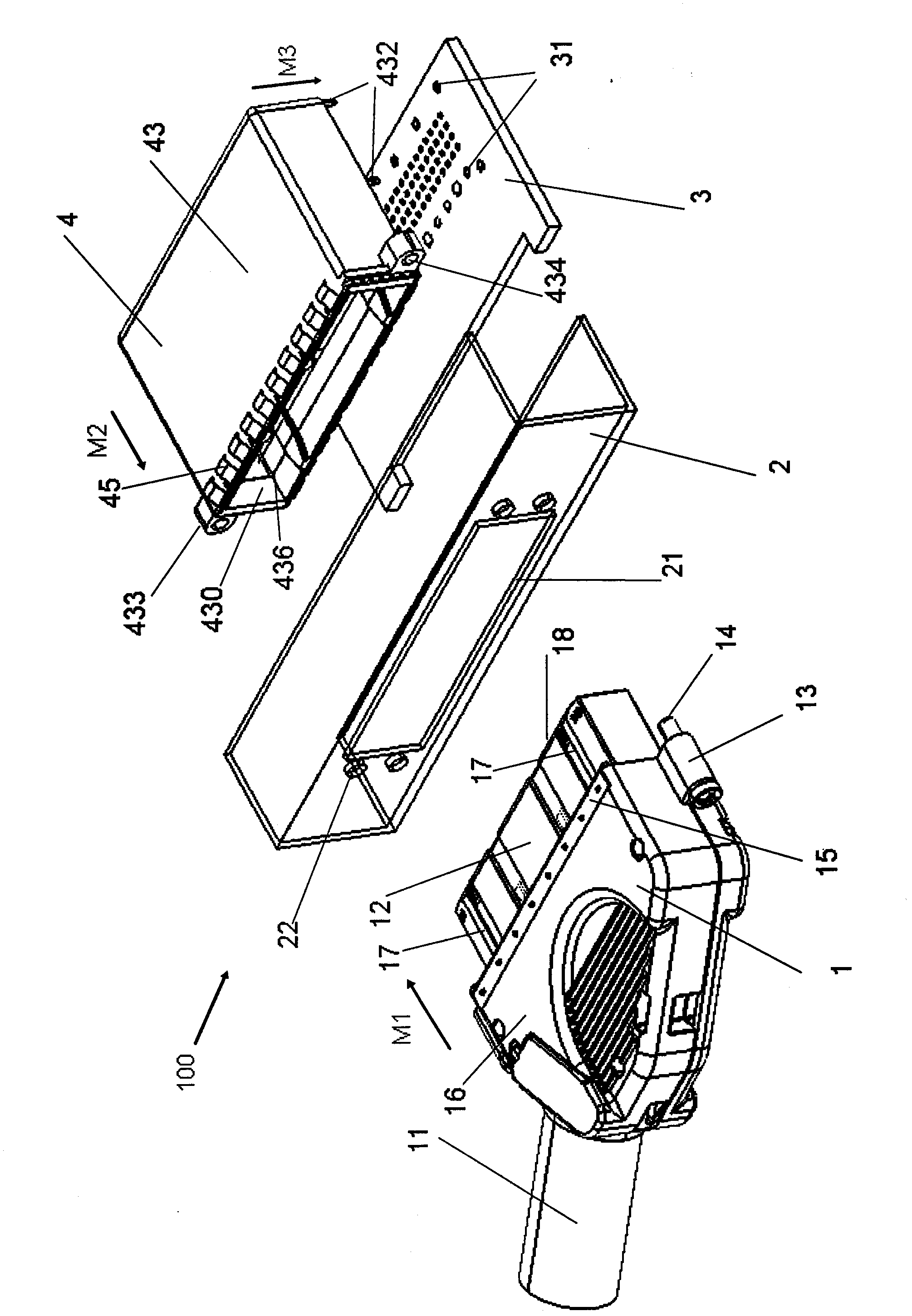
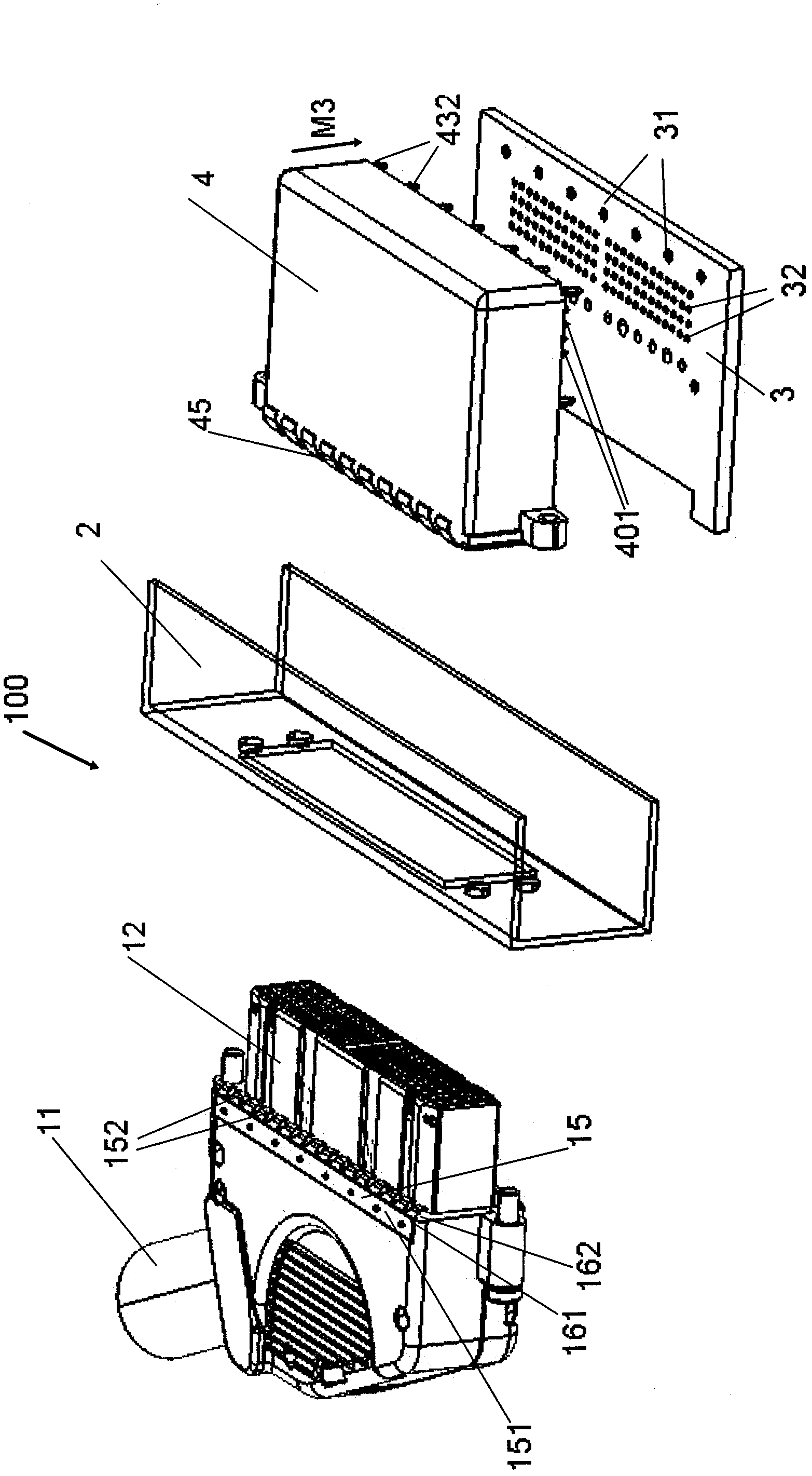
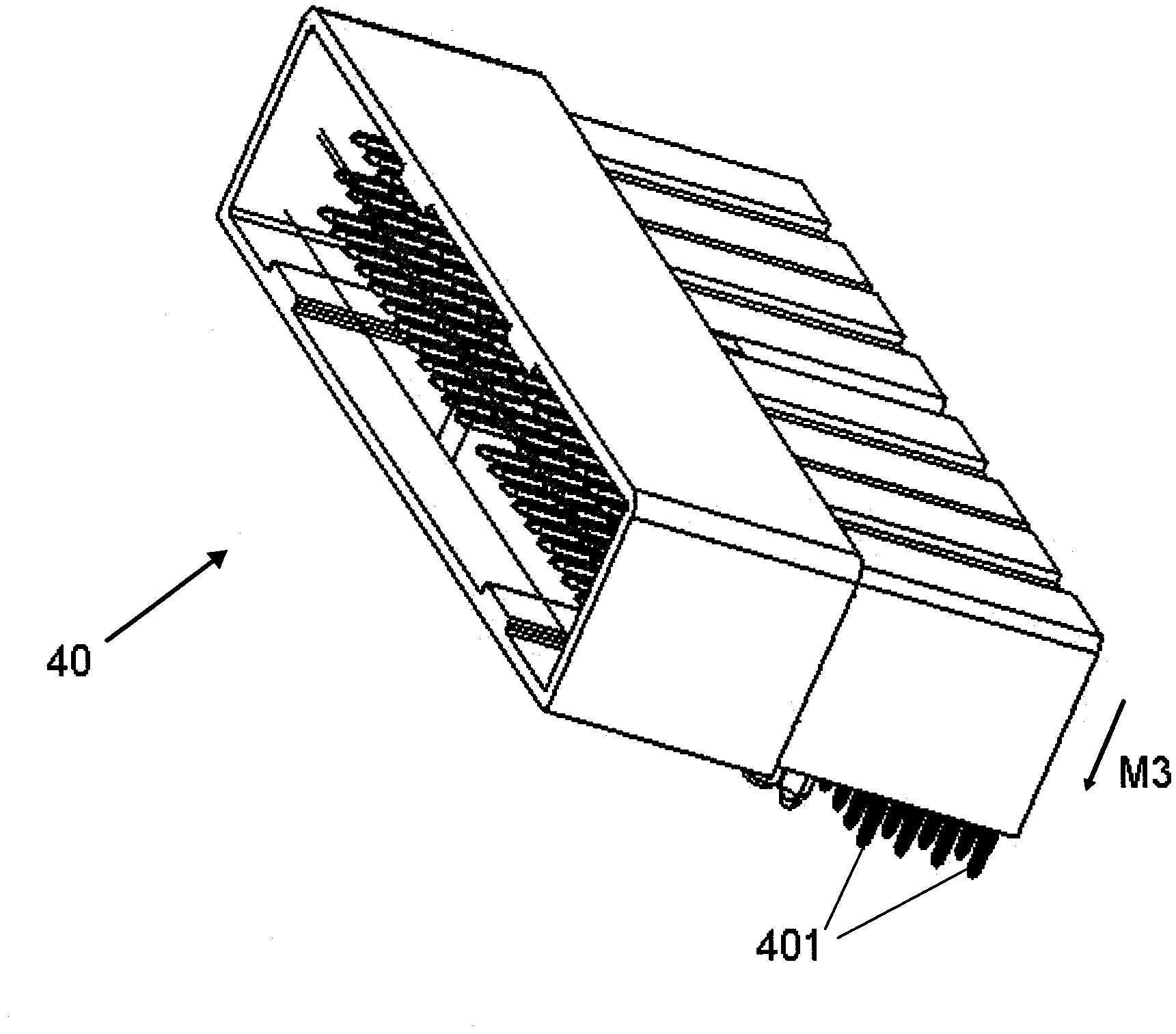
[0037] figure 1 The connector assembly according to the present invention is shown in an exploded view at a first viewing angle, the connector assembly 100 comprising a plug connector 1 , a mounting panel 2 with a preferably U-shaped cross-section, a socket connector 4 and a circuit board 3 . figure 2 The connector assembly 100 is shown in an exploded view in a second viewing angle. Hereinafter, for the convenience of description, the mating side of the plug connector and the receptacle connector is referred to as the mating side.

[0038] In this exemplary embodiment, a plug connector 1 is connected to a cable 11, also referred to in this context as a line-end connector, and a socket connector 4 is connected to a circuit board 3, also referred to in this context as a board-end connector. . The plug connector 1 includes a shield housing 16 and a first mating portion 12 extending from the shield housing 16 in an assembly direction M1. The first mating part 12 has an insula...


PUM


Abstract

The invention relates to a wire terminal connecting device comprising a shield shell body and at least one terminal, wherein a conductive structure is arranged in the shield shell body, a matching part extends from the shield shell body along the matching direction and is provided with an insulation shell body, the at least one terminal is arranged in the insulation shell body, the shield shell body is provided with a matching side edge along the matching direction, a conductive elastic piece is arranged on the matching side edge of the shield shell body, and the conductive elastic piece is in electrical connection with the conductive structure in the shield shell body. The invention further relates to a plate terminal connecting device comprising a conductive outer shell and a connecting device shell body located in the conductive outer shell, wherein at least one terminal is arranged on the connecting device shell body, the conductive outer shell limits a matching part which is provided with a matching side edge along the matching direction, a conductive elastic piece is arranged on the matching side edge of the matching part, and the conductive elastic piece is in electrical connection with the conductive outer shell. Besides, the invention further relates to a corresponding plate terminal connecting device assembly and a corresponding connecting device assembly.

Description

technical field [0001] The invention relates to a connector with electrostatic discharge protection, grounding protection and shielding protection and a corresponding connector assembly. Background technique [0002] When electrically connecting two objects or devices through the connectors of a connector assembly, it is often found that the contact points which should be at the respective "ground" potentials of the two connectors or devices are at different voltages. Such voltage differences may be attributed to charging phenomena caused by static electricity or stray electric fields. The latter process is enhanced once one of the connected devices includes a long section that can act as an antenna, such as a shielded cable. The established mutual voltage difference may rise to hundreds of volts, or even accumulate to thousands of volts. [0003] When connected, devices that are at different voltages will discharge so that both devices are at the same potential, eliminati...

Claims


Application Information

Patent Timeline
IPC IPC(8): H01R13/648H01R13/02H01R24/00
Inventor 鲁向前
Owner FCI ASIA PTE LTD
Learn More