
bms multi-machine parallel realization system

A technology that realizes system and parallel connection, applied in the field of electronics, can solve problems such as overcurrent, overvoltage, negative pressure, etc., and achieve the effect of eliminating pressure difference and not easy to consume electricity.

Active Publication Date: 2022-04-26
HANGZHOU BMSER TECH
View PDF10 Cites 0 Cited by
  • Summary
  • Abstract
  • Description
  • Claims
  • Application Information

AI Technical Summary

Problems solved by technology

[0005] The purpose of the present invention is to provide a BMS multi-machine parallel realization system, which is used to solve the problems of overcurrent, overvoltage and negative pressure caused by hot swapping of battery packs in the prior art

Method used


Image

  • bms multi-machine parallel realization system
  • bms multi-machine parallel realization system
  • bms multi-machine parallel realization system

Examples


Embodiment Construction

[0031] Preferred embodiments of the present invention will be described in detail below with reference to the accompanying drawings, but the present invention is not limited to these embodiments. The present invention covers any alternatives, modifications, equivalent methods and schemes made within the spirit and scope of the present invention.

[0032] In order to provide the public with a thorough understanding of the present invention, specific details are set forth in the following preferred embodiments of the present invention, but those skilled in the art can fully understand the present invention without the description of these details.

[0033] In the following paragraphs the invention is described more specifically by way of example with reference to the accompanying drawings. It should be noted that all the drawings are in a simplified form and use imprecise scales, which are only used to facilitate and clearly assist the purpose of illustrating the embodiments of ...


PUM


Abstract

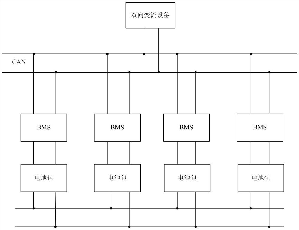
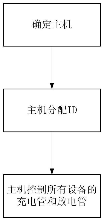
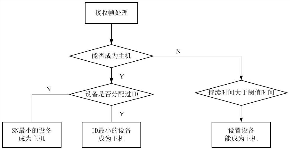
The present invention proposes a BMS multi-machine parallel realization system. Multiple BMSs are connected in parallel and connected to bidirectional converter devices through CAN bus. Multiple battery packs corresponding to multiple BMSs are connected in parallel. Each BMS has a device code. The following steps are adopted Implementation: Determine a management system from the multiple BMSs described above as the master, and other BMSs as slaves; the master assigns IDs to the slaves according to the ID allocation table; the master controls the charging tubes of the master and slaves according to the obtained slave information and discharge tube so that the corresponding BMS is connected in parallel. The invention does not need an additional host, and the host is not fixed, so it is convenient to add parallel BMSs.

Description

technical field [0001] The invention relates to the field of electronic technology, in particular to a BMS multi-machine parallel realization system. Background technique [0002] In the existing energy storage system, due to the different demands on capacity and power, a single set of batteries can no longer meet the demand. It is necessary to connect multiple sets of batteries in parallel to increase the capacity and maximum charge and discharge current of the battery. When two sets of batteries are connected in parallel, they can be directly connected in parallel only when the voltages are relatively close. When there is a voltage differential, the higher voltage battery pack will charge the lower voltage battery pack. Due to the small internal resistance of the battery, when the voltage difference is large, the charging current will be too large, resulting in battery damage. [0003] In the existing solution, one master is fixed in the parallel BMS for management, and ...

Claims


Application Information

Patent Timeline
Patent Type & Authority Patents(China)
IPC IPC(8): H01M10/42H01M10/44H01M10/46H02J7/00
CPCH01M10/4207H01M10/425H01M10/441H01M10/46H02J7/0013H02J7/0014H02J7/0016H02J7/0019H02J7/0068H01M2010/4271H01M2010/4278Y02E60/10
Inventor 夏圣金周逊伟
Owner HANGZHOU BMSER TECH
Learn More