Optical cable fault analysis method and system

A fault analysis method and fault analysis technology, applied in the transmission system, electromagnetic wave transmission system, electrical components, etc., can solve the problems of inaccurate fault location, large error, high hardware cost, etc., and achieve rich methods, fast and accurate positioning, The effect of protecting existing investments

Active Publication Date: 2016-11-30
POWER DISPATCHING CONTROL CENT OF GUANGDONG POWER GRID CO LTD
View PDF4 Cites 1 Cited by
  • Summary
  • Abstract
  • Description
  • Claims
  • Application Information

AI Technical Summary

Problems solved by technology

[0011] Based on this, it is necessary to provide an optical cable fault analysis method and system for the above-mentioned problems of high hardware cost, inaccurate fault location and large error

Method used


Image

  • Optical cable fault analysis method and system
  • Optical cable fault analysis method and system
  • Optical cable fault analysis method and system

Examples


Embodiment Construction

[0027] The technical solutions of the present invention will be further described below in conjunction with the accompanying drawings and specific embodiments.

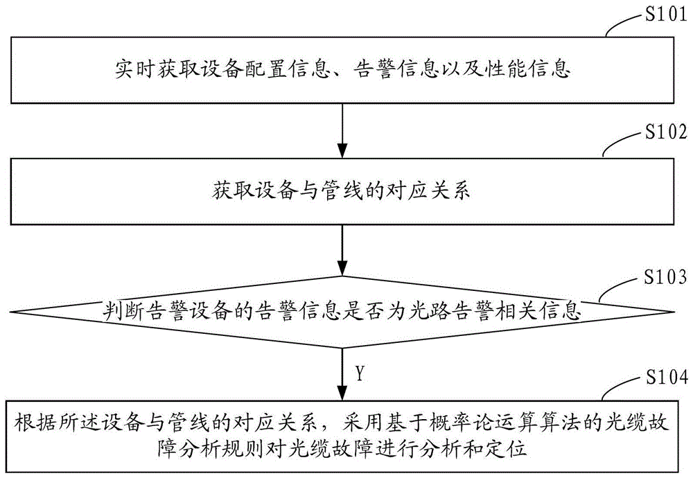
[0028] see figure 1 Shown, a kind of optical cable fault analysis method comprises the following steps:

[0029] Step S101, acquiring device configuration information, alarm information, performance information, etc. in real time.

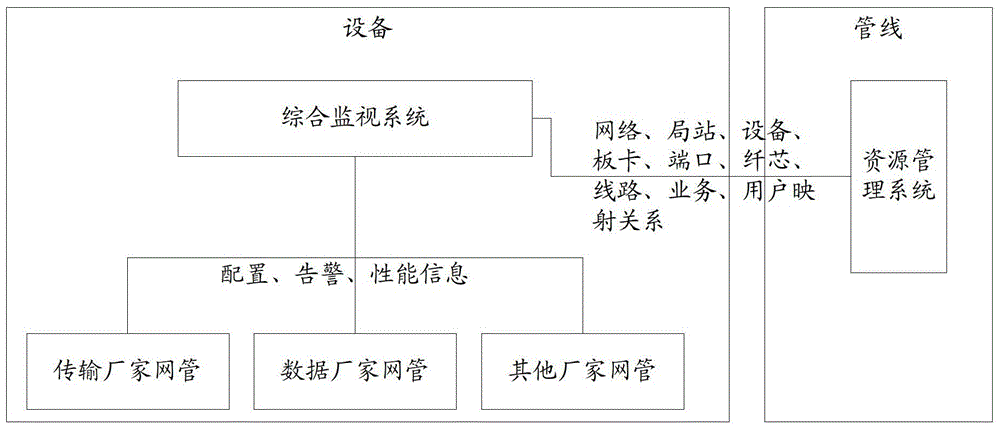
[0030] As a better embodiment, the process of obtaining device configuration information, alarm information and performance information may specifically include: the integrated monitoring system obtains the information of the device from the network management of the transmission manufacturer and the network management of the data manufacturer through socket, FTP, web service and other interfaces. Configuration information, alarm information, performance information, etc.

[0031] Step S102, obtaining the corresponding relationship between equipment and pipelines.

[0032] For a better ...


PUM


Abstract

The present invention provides an optical cable fault analysis method and system. The method includes the following steps: acquiring equipment configuration information, alarm information and performance information in real time; acquiring the corresponding relationship between equipment and pipelines; judging whether the alarm information of the alarm equipment is related to optical path alarms information; if so, according to the corresponding relationship between the equipment and the pipeline, the optical cable fault analysis rule based on the probability theory operation algorithm is used to analyze and locate the optical cable fault; the process specifically includes: analyzing the optical path interruption in real time according to the optical path alarm related information , and then analyze the interruption of the optical cable segment according to the interrupted optical path obtained through analysis. The optical cable fault analysis method and system of the present invention realize fast and accurate positioning of optical cable faults, and can effectively save the hardware investment cost of using the OTDR method for optical cable fault analysis.

Description

technical field [0001] The invention relates to the field of electric power communication, in particular to an optical cable fault analysis method and an optical cable fault analysis system. Background technique [0002] In the actual operation of communication optical cables, they are often interrupted due to factors such as man-made damage, poor construction quality, or natural environmental influences. When this happens, it is necessary to analyze and locate the cause of the cable failure in time to find out the fault point. [0003] The traditional optical cable fault analysis method generally uses OTDR (Optical Time Domain Reflectometer, optical time domain reflectometer) to measure the distance of the fault point, and compares the physical length of the optical cable to obtain the length of the fault point of the optical cable, and selects the corresponding optical cable connection point as a geographical reference. Points to delineate the fault area, and then organiz...

Claims


Application Information

Patent Timeline
Patent Type & Authority Patents(China)
IPC IPC(8): H04B10/075H04B10/071
Inventor 何杰亢中苗梁文娟胡俊杨李溢杰付佳佳林斌
Owner POWER DISPATCHING CONTROL CENT OF GUANGDONG POWER GRID CO LTD
Why Eureka
Try Eureka