Rolling stand with roll bearing

A roll and support technology, which is applied in the field of roll supports with roll support devices, can solve the problems of high cost and necessary replacement

Inactive Publication Date: 2013-04-10
ANDRITZ AG
View PDF9 Cites 3 Cited by
  • Summary
  • Abstract
  • Description
  • Claims
  • Application Information

AI Technical Summary

Problems solved by technology

This modification is very expensive in the case of conventional trains, since the work rolls and, if necessary, the intermediate rolls and the entire roll support have to be replaced for this purpose
In some cases it is even necessary to replace the entire bearing

Method used


Image

  • Rolling stand with roll bearing
  • Rolling stand with roll bearing
  • Rolling stand with roll bearing

Examples


Embodiment Construction

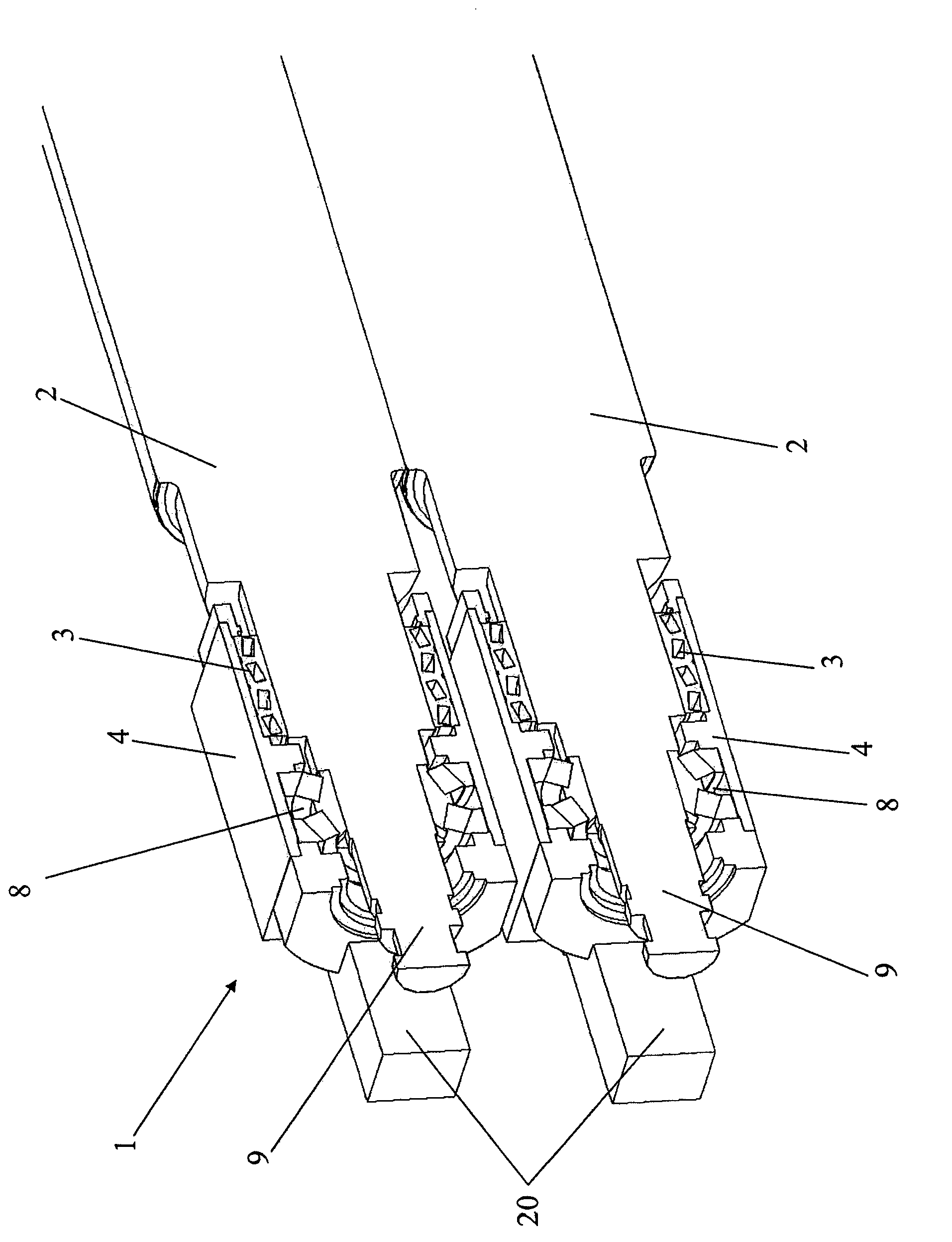
[0023] figure 1 The middle table shows a conventional rolling installation 1 with an axial displacement device according to the prior art. The work roll 2 is embodied in one piece. They are supported in the one-piece work roll insert 4 via a radial bearing 3 and an axial bearing 8 arranged on the roll head 9 . The bearing cap 20 is screwed onto the roll insert 4 . The axial force is transmitted to the work roll 2 via the axial bearing 8 .

[0024] In order to transform the traditional rolling equipment without axial movement into figure 1 Rolling installations with axial displacement have previously had to replace at least the entire work roll and the entire roll insert.

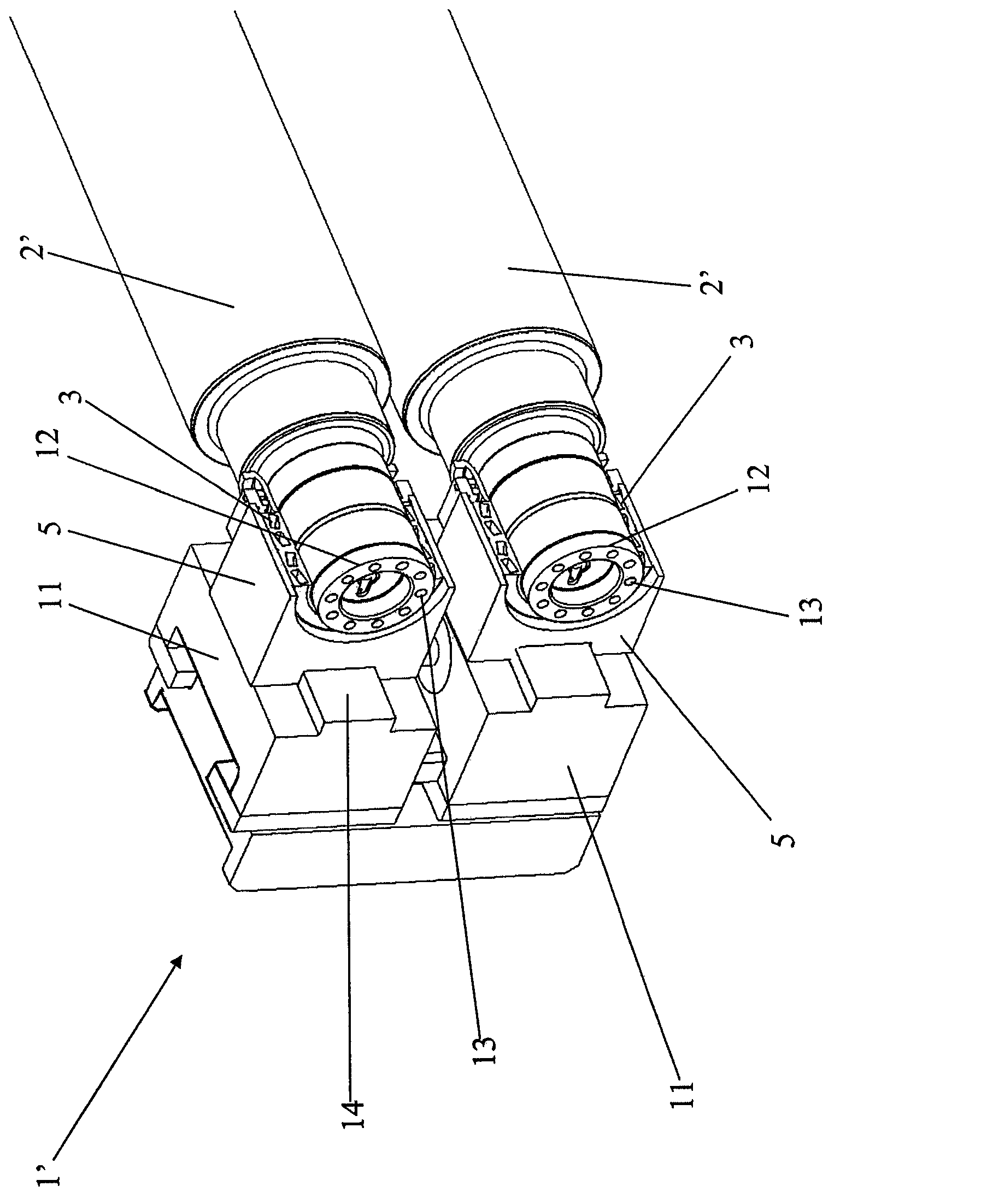
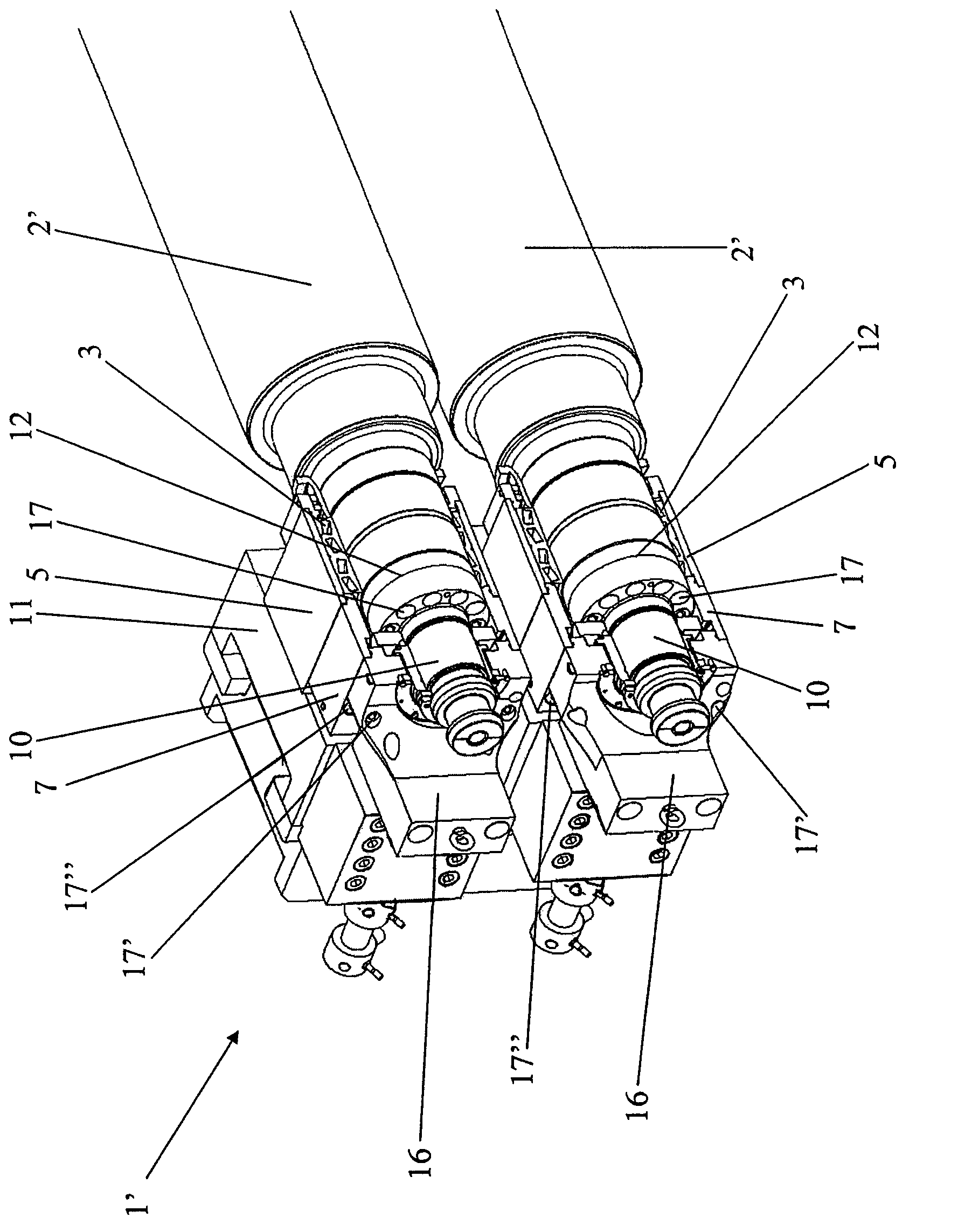
[0025] figure 2 A rolling installation 1' according to the invention is shown, wherein neither the axial locking mechanism nor the axial displacement device is shown here for better illustration.

[0026] The work rolls 2' are supported with radial bearings 3 in roll inserts 5 for axial support, respe...


PUM


Abstract

The present invention relates to a rolling apparatus (1') having work rolls (2') and, if appropriate, having intermediate rolls, which are mounted in a rolling stand by means of roll chocks (5) via radial bearings (3). The special design of the rolling apparatus (1') makes it possible to retrofit the rolling apparatus (1') with an axial displacement device (18) with particular ease. The present invention also relates to a process for converting, in particular for subsequently converting, a rolling stand without an axial displacement device into a rolling stand with an axial displacement device.

Description

technical field [0001] A rolling installation with work rolls and possibly intermediate rolls, which are supported in roll supports by means of roll inserts via radial bearings, forms the subject of the invention. A method for converting, in particular retrofitting, a roll stand with work rolls and / or intermediate rolls without axial displacement to a roll stand with axial displacement also forms the subject matter of the present invention. Background technique [0002] In roll stands for cold-rolled strip, it is known in the art that the work rolls or intermediate rolls are movable relative to each other in the axial direction (transversely to the direction of strip travel). This is used in conjunction with a variable diameter of the rolls in the axial direction (ground) as an additional adjustment element for influencing the flatness of the strip. [0003] The roll shifter is generally used for widening the flatness adjustment range with the use of a separate roll grindin...

Claims


Application Information

Patent Timeline
Patent Type & Authority Applications(China)
IPC IPC(8): B21B13/14B21B37/40
CPCB21B31/18B21B13/142B21B37/40B21B2269/12
Inventor 彼得·彭切弗赫伯特·绍普迈尔安德烈亚斯·拉布
Owner ANDRITZ AG
Why Eureka
Try Eureka