Omni wheel assembly and Omni vehicle

An omnidirectional wheel and vehicle technology, applied in the directions of wheels, vehicle components, elastic suspension, etc., can solve the problems of complicated and expensive transmission, and achieve the effect of optimizing operation and simplifying use.

Inactive Publication Date: 2015-11-25
约翰·维克托·加诺
View PDF7 Cites 0 Cited by
  • Summary
  • Abstract
  • Description
  • Claims
  • Application Information

AI Technical Summary

Problems solved by technology

Regarding the engine, the transmission of power from the engine to the wheels is complex and expensive

Method used


Image

  • Omni wheel assembly and Omni vehicle
  • Omni wheel assembly and Omni vehicle
  • Omni wheel assembly and Omni vehicle

Examples


Embodiment Construction

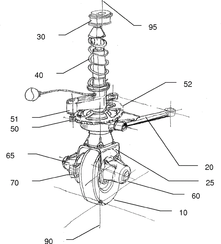
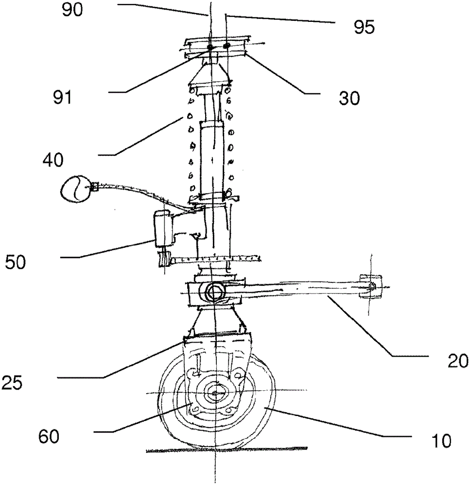
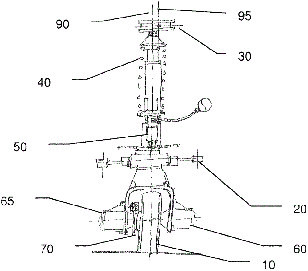
[0029] figure 1 The omnidirectional wheel assembly shown in includes a wheel 10 mounted on a fork 25 and capable of rotating 360° about a pivot axis 90 . This capability allows a vehicle equipped with this omnidirectional wheel assembly to steer in all directions. Users can easily steer vehicles to park in lots with narrow access or to move in traffic jam situations. In this object, the assembly is equipped with a steering mechanism 50 comprising a steering motor 51 engaged with a circular steering rack. In addition, the assembly includes two electric motors 60, 65 for applying moving force to the vehicle, although one motor may be sufficient, and braking equipment 70 for stopping the vehicle if required. The suspension assembly 40 includes suspension springs connected to suspension dampers. The assembly is connected to the vehicle via a lower suspension arm 20 and an upper connection joint 30 . These two elements define the geometry of the wheel assembly in the vehicle an...


PUM


Abstract

An omni-directional wheel assembly for a vehicle that includes a wheel, at least one lower suspension link and an upper attachment joint. Both the at least one lower suspension link and the upper attachment joint are attachable to the vehicle. The wheel is able to rotate at 360°, to steer the vehicle, around a pivot line positioned by the at least one lower suspension link and the upper attachment joint once attached to the vehicle. A projection of the pivot line onto a vertical projection plane comprises a vertical axis passing through a contact point between the wheel and ground defining a caster angle with the vertical axis, where whatever the orientation of the projection plane, the omni-directional wheel assembly includes an adjustment means able to adjust the caster angle within a predetermined range.

Description

technical field [0001] The present invention relates to wheel assemblies and in particular to omnidirectional wheel assemblies and to electric omnidirectional vehicles equipped with such omnidirectional wheel assemblies. Background technique [0002] It is known from the prior art to provide omnidirectional vehicles in different ways. For example, document WO2010 / 150286 describes a five-wheeled vehicle. Each wheel is capable of rotating 360° about a pivot axis to enable movement of the vehicle in all directions. The vehicle is driven by a central wheel equipped with an electric motor. The pivot axes of the front and rear wheels may be tilted forward or rearward. The vehicle exhibits the disadvantage of unstable behavior when moving in lateral direction, since the position of the pivot axis results in asymmetrical stresses on the tires and does not provide the steering mechanism with any self-centering for steering. This phenomenon is even worse if the wheels are driven, ...

Claims


Application Information

Patent Timeline
Patent Type & Authority Patents(China)
IPC IPC(8): B62D7/02
CPCB60G7/006B60B19/003B60G3/01B60G2300/37B60K7/0007B62D7/026B62D7/1509B60B19/00B62D7/02
Inventor 约翰·维克托·加诺恩里克·赫克托·斯卡拉布罗尼
Owner 约翰·维克托·加诺
Why Eureka
Try Eureka