Charging Bus

Inactive Publication Date: 2020-05-07
SHELTON CHRISTOPHER
View PDF2 Cites 0 Cited by
  • Summary
  • Abstract
  • Description
  • Claims
  • Application Information

AI Technical Summary

Benefits of technology

The invention allows for independent management of each battery source, so that each battery operates optimally. This means that each battery can be controlled separately, which can improve performance and efficiency.

Problems solved by technology

However, known systems suffer from a number of problems relating to the mismanagement of the power.
1. The use of a solar panel to charge a 12v battery. Such panels usually comprise 36 silicon cells which provide constant current charging at whatever the voltage of the battery—for example 13v. But solar panels are rated at their maximum power point which is commonly a voltage of around 17v. In this instance a 170 W panel would provide 10 A at 17V but would still supply 10 A when connected to a 13v battery and thus deliver only 130 W.
2. An alternator on an engine is generally designed to maintain a starting battery. Such a battery is ideally rarely used and so remains fully charged and ready to start the engine. The alternator is fitted with a regulator so as not to overcharge the battery. In general alternator will charge the battery eventually but will take a long time because as the voltage rises towards the fully charged value, the alternator regulator reduces the current to small amounts. If the battery is used for some other purpose such as lighting, the alternator will behave in the same way and the battery will take some time to reach a fully charged state. A battery is best charged rapidly by delivering current as much as is available. Lead-acid batteries react to this by raising their voltage and so making it hard to deliver the charge. If the source voltage is raised the charge is delivered but care must be taken so as to not over-charge the battery by sensing when the battery charge state is reaching maximum.
3. This problem is compounded when two batteries must be charged from the same source. It is common practice to provide diodes in a mains-powered charger so that several batteries can be charged at the same time. Such diodes prevent the loads from one battery from discharging another but also prevent the batteries from being optimally charged. For example if one battery is fully charged the raised voltage method can be used to get charge in more rapidly than the battery already charged will become over-charged; if the standing voltage method is used the discharged battery will take a long time to charge.
4. It is very difficult to charge batteries with different chemistry simultaneously such as wet lead-acid, gel lead-acid, nickel-cadmium or lithium by connecting them with diodes as each has a different charge regime and voltage.

Method used


Image

  • Charging Bus
  • Charging Bus

Examples


Embodiment Construction

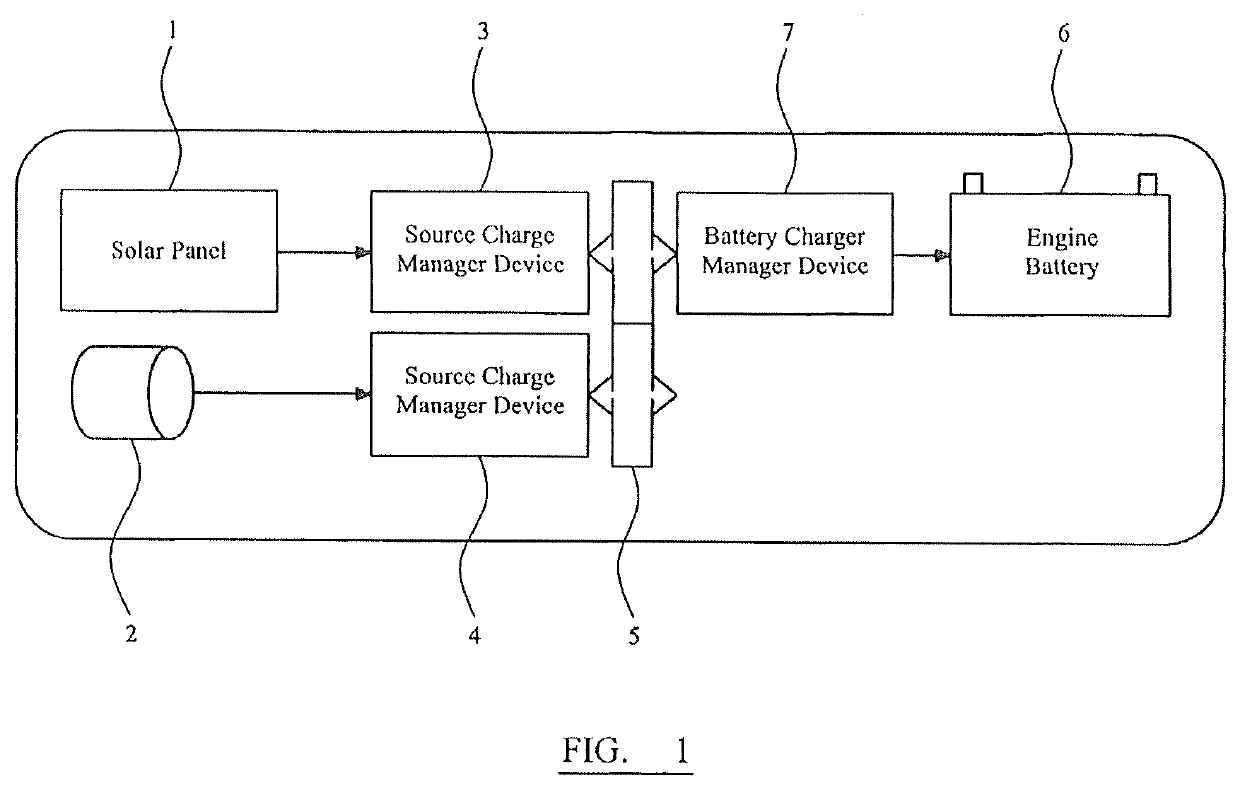
[0018]FIG. 1 shows schematically an arrangement of the charging bus. The boat is provided with a first power source, solar panels 1 and a second power source, engine alternator 2. Each of the power sources 1, 2 is connected to a respective manager device 3, 4, which in turn is connected to a charging rail5. A battery 6 is connected via charging manager 7 to the charging rail 5. The rail voltage can be chosen to be any particular voltage or range of voltage.

[0019]The basic method of operation is that sources of a lower voltage than the rail 5 get their power delivered at Rail voltage by a method which increases the voltage by the use of the respective manager device 3,4 such as an active or switching converter and sources with a voltage higher than Rail use a voltage dropping method, preferably lossless, by the respective manager device 3,4 such as a switching converter. Each such converter will be appropriate to the needs of the source as in the following examples:

[0020]1. A solar p...


PUM


Abstract

An apparatus for the management of one or more power sources when connected to one or more batteries, in particular on a boat, comprises a first power source such as an engine alternator 11 connected to a first source charge manager 26 and a second power source such as a solar panel 13,14 connected to a second source charge manager 26. The first and second source charge managers 26 are connected to a rail 5 maintained over a predetermined range of voltage. The rail 5 is connected to a battery charge manager 33, which manager is connected to a battery such that the battery can be charged from at least one of the first and second power sources.

Description

CROSS-REFERENCES TO RELATED APPLICATIONS[0001]This non-provisional patent application is a continuation of U.S. patent application Ser. No. 15 / 037,873. The earlier application listed the same inventor.STATEMENT REGARDING FEDERALLY SPONSORED RESEARCH OR DEVELOPMENT[0002]Not ApplicableMICROFICHE APPENDIX[0003]Not ApplicableBACKGROUND OF THE INVENTION1. Field of the Invention[0004]The invention relates to an apparatus and method for the management of one or more power sources when connected to one or more batteries, in particular in an environment without access to mains electricity such as on a boat.2. Description of the Related Art[0005]Modern small and medium sized boats are provided with a variety of electrical equipment on board such as refrigerators, which are adapted to be powered off an on-board battery. This battery is also sometimes used for starting the on-board engine and will typically be a 12V marinised lead-acid battery. To avoid the risk that the refrigerator and other ...

Claims


Application Information

Patent Timeline
IPC IPC(8): H02J7/35H02J7/00B63H21/17
CPCH02J7/00036B63H2021/171B63H21/17H02J7/35B63J3/04H02J7/1423H02J9/002H02J7/0048H02J2207/40H02J2310/42
Inventor SHELTON, CHRISTOPHER
Owner SHELTON CHRISTOPHER
Why Eureka
Try Eureka