Chemical-looping combustion method with ashes and fines removal in the reduction zone and plant using same

Active Publication Date: 2014-10-02
TOTAL PUTEAUX FR +1
View PDF12 Cites 2 Cited by
  • Summary
  • Abstract
  • Description
  • Claims
  • Application Information

AI Technical Summary

Benefits of technology

[0097]Furthermore, in cases where the oxygen-carrying particles undergo mechanical degradation (attrition) leading to the creation of fines, it is possible to adjust the operating conditions of the separation zone so as to not only eliminate the combustion fly ashes, but also the fine particles of oxygen-carrying material that have undergone attrition. Under these new conditions, the operation of the plant is optimum when the flow of separated ashes entrained with

Problems solved by technology

Chemical-looping combustion of solid feeds requires severe and compelling operating conditions to be able to conduct the combustion reactions.
Another problem linked with chemical-looping combustion of solid feeds relates to the formation of ashes.
The grain size of the agglomerated ashes is more delicate to estimate and depends on the conditions of implementation of the method.
Besides, the high gas rates operated in the circulating fluidized-bed reduction reactor do not allow to obtain sufficient particle residence times for gasifying all of the solid fuel, then for carrying out combustion of the gasification products.
Now, separation of the unburnt particles from the oxide particles is delicate because it requires additional gas supply in large amounts, which is energy consuming.
Moreover, due to too short a residence time, it is difficult to carry out total combustion and the fumes contain large amounts of CO and H2, which involves the presence of a post-combustion

Method used


Image

  • Chemical-looping combustion method with ashes and fines removal in the reduction zone and plant using same
  • Chemical-looping combustion method with ashes and fines removal in the reduction zone and plant using same
  • Chemical-looping combustion method with ashes and fines removal in the reduction zone and plant using same

Examples


Example

EXAMPLE

[0136]The example below illustrates the invention using the simulation of the operation of a 3-MWth plant.

[0137]This plant is supplied with coal at a flow rate of 420 kg / h characterized by an ash content of 13.9 wt. % and a volatile content of 29.9%.

[0138]The coal is supplied in the fuel reactor with a grain size characterized by the fact that less than 2% of the coal has a particle size above 200 microns.

[0139]The grain size composition of the oxygen-carrying material is such that more than 90% of the grains ranges between 150 and 300 microns, and the density of the oxygen-carrying material is close to 4000 kg / m3.

[0140]The grain size distribution of the fly ashes is given by way of example in FIG. 3.

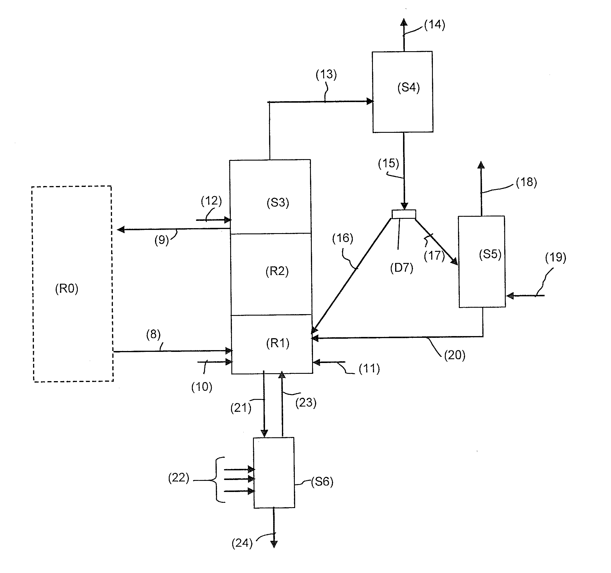
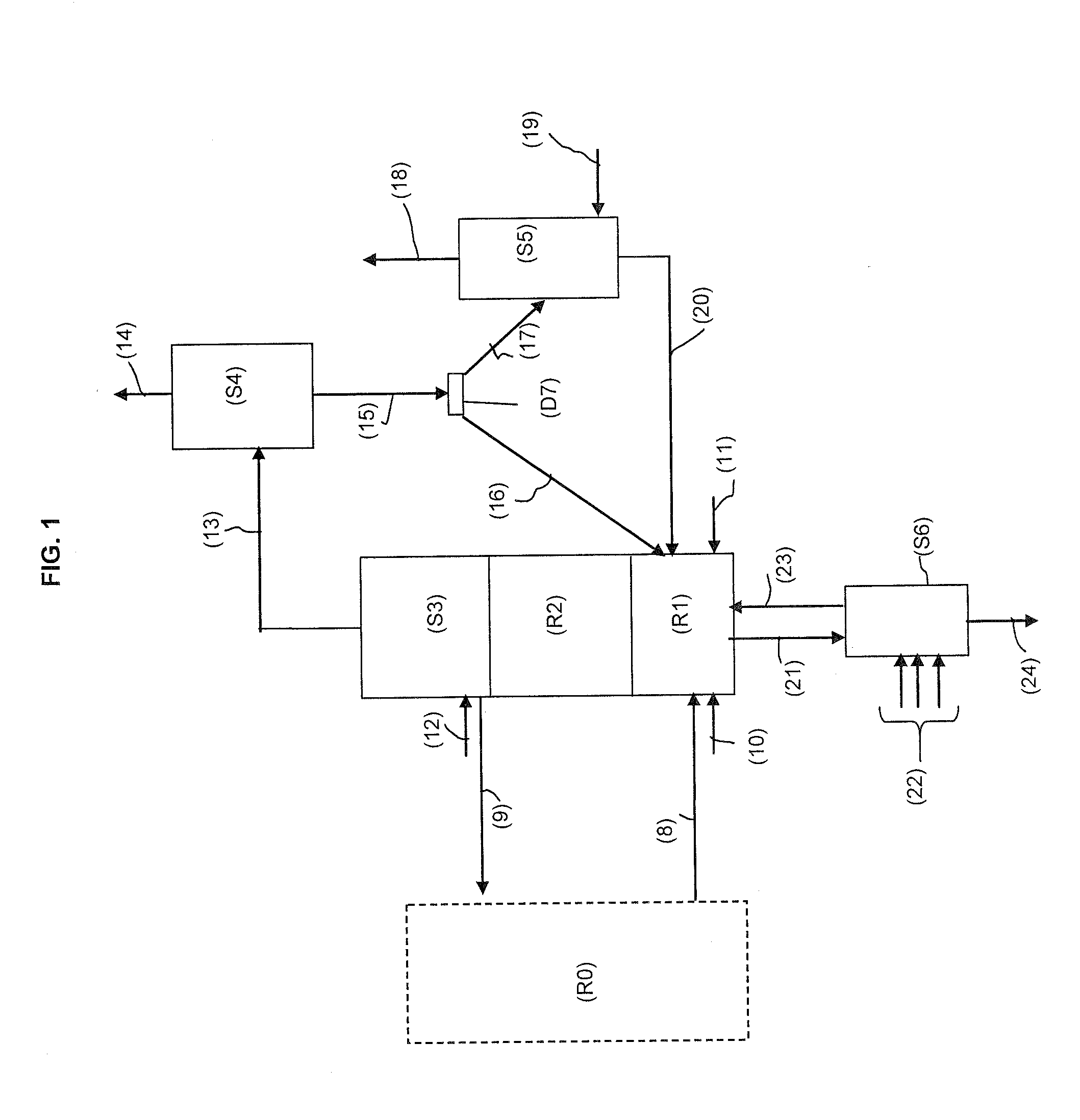
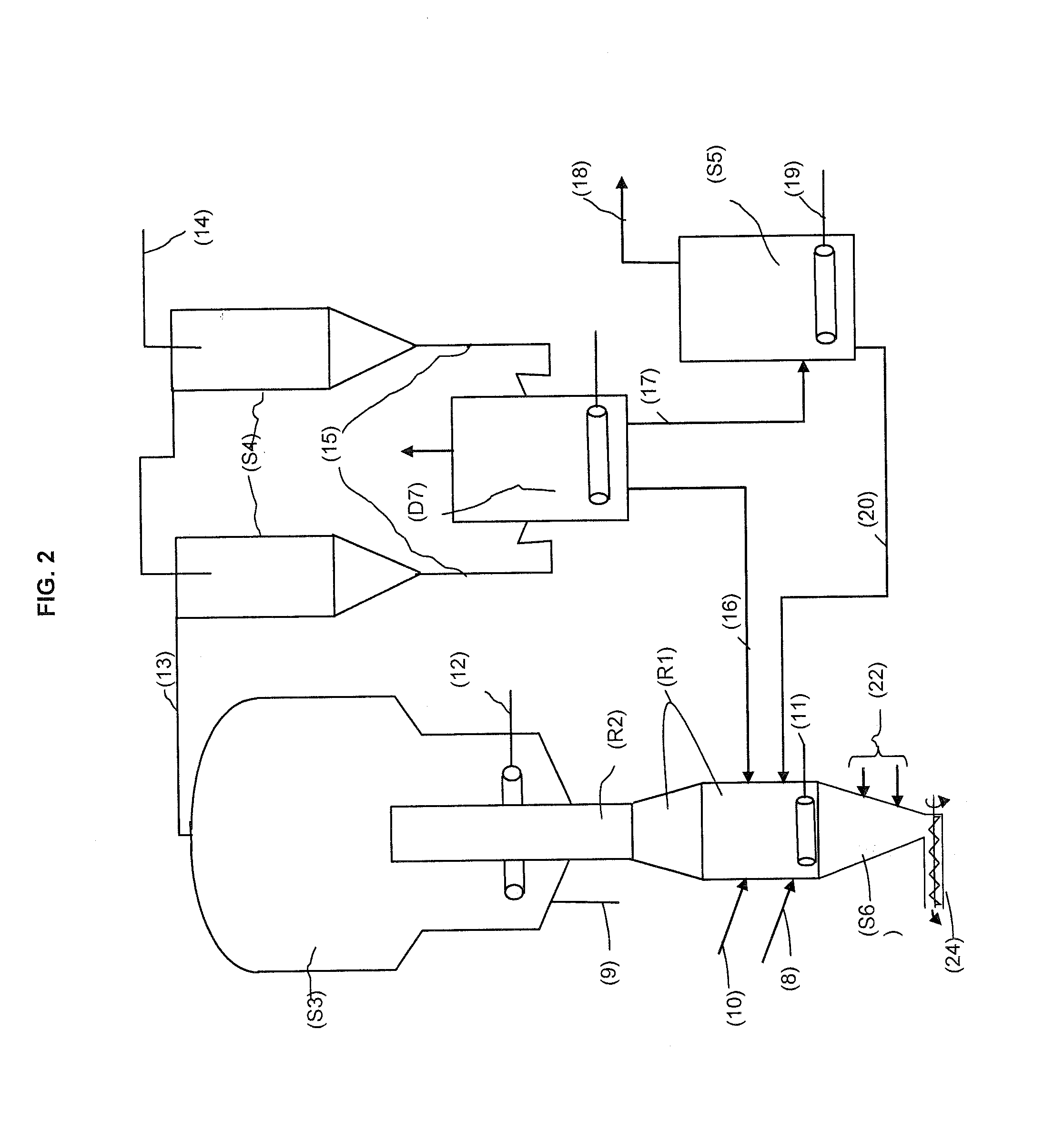
[0141]The fuel reactor is made up of 3 zones:[0142]a first reaction zone R1 for contacting solid feed particles in the presence of metallic oxide particles under dense fluidized bed conditions;[0143]a dilute phase combustion zone (second reaction zone R2) for the gaseous effluent...


PUM


Abstract

The invention relates to an improved method for chemical-looping combustion of a solid hydrocarbon-containing feed using a particular configuration of the reduction zone with: a first reaction zone R1 operating under dense fluidized bed conditions; a second reaction zone R2; a fast separation zone S3 for separation of the unburnt solid feed particles, of fly ashes and of the oxygen-carrying material particles within a mixture coming from zone R2; fumes dedusting S4; a particle stream division zone D7, part of the particles being directly recycled to first reaction zone R1, the other part being sent to an elutriation separation zone S5 in order to collect the ashes through a line 18 and to recycle the dense particles through a line 20 to first reaction zone R1.
The invention also relates to a chemical-looping combustion plant allowing said method to be implemented.

Description

FIELD OF THE INVENTION[0001]The invention relates to the sphere of chemical-looping oxidation-reduction (redox) combustion of solid hydrocarbon-containing feeds in order to produce energy, syngas and / or hydrogen.[0002]More particularly, the invention relates to the removal of ashes produced in the reduction reactor of the chemical-looping combustion plant.[0003]Terminology[0004]Chemical-Looping Combustion or CLC: In the text hereafter, what is referred to as a CLC (Chemical-Looping Combustion) is a loop redox process on active mass. It can be noted that, in general, the terms oxidation and reduction are used with regard to the oxidized or reduced state of the active mass respectively. In a chemical-looping combustion plant, the oxidation zone is where the redox mass is oxidized and the reduction zone is where the redox mass is reduced.[0005]Devolatilization[0006]During thermal treatment, the organic compounds lose volatiles, first water and carbon dioxide, liquid and then gaseous hy...

Claims


Application Information

Patent Timeline
IPC IPC(8): F23C10/01F23C10/24F23J1/00F23C10/10
CPCF23C10/005F23C10/10F23C10/24F23C99/00F23C2900/99008Y02E20/346B01J8/26B01J8/32B01J2208/00513F23C10/01F23J1/00B01J8/1827Y02E20/34
Inventor GAUTHIER, THIERRYHOTEIT, ALIGUILLOU, FLORENTRIFFLART, SEBASTIEN
Owner TOTAL PUTEAUX FR
Why Eureka
Try Eureka