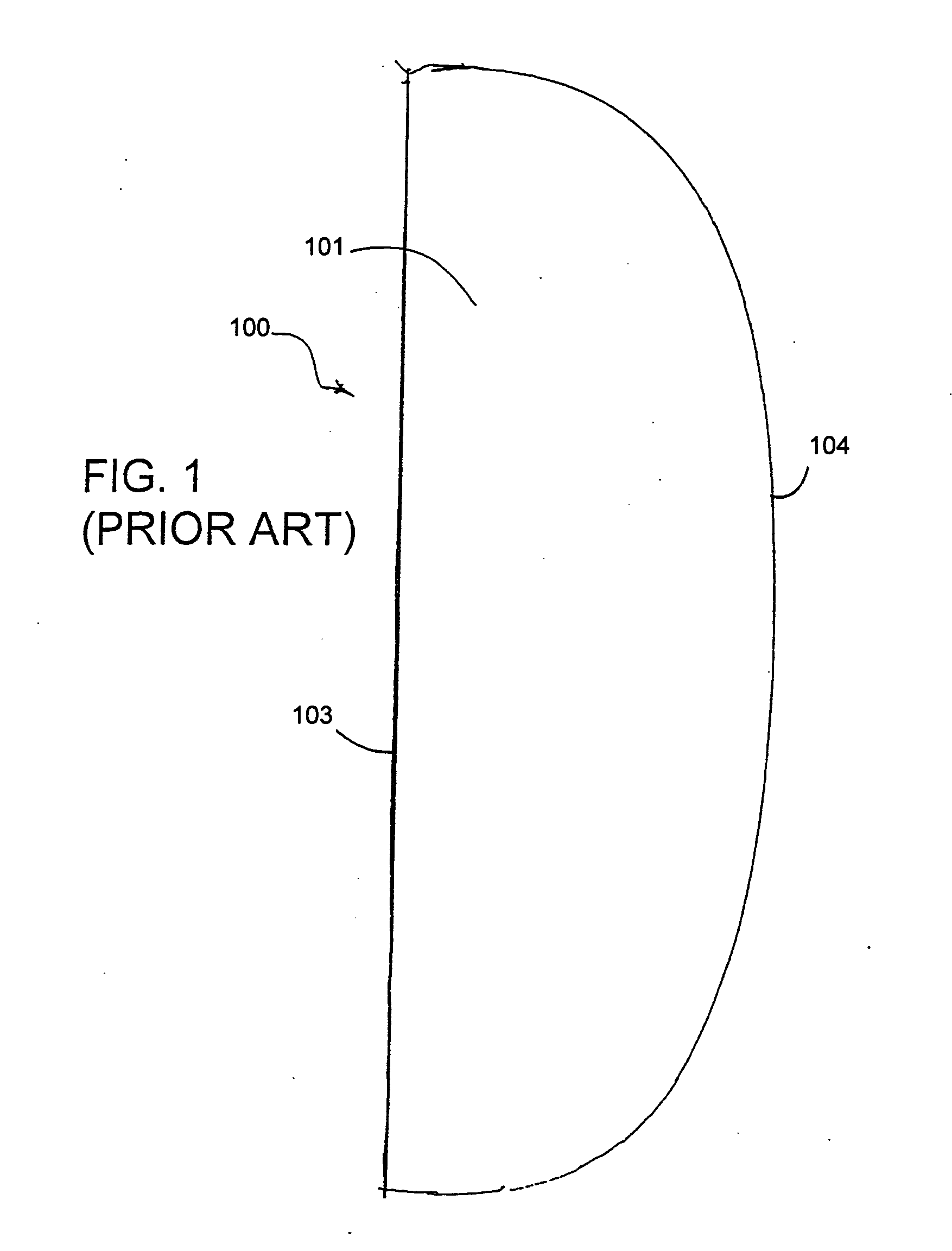
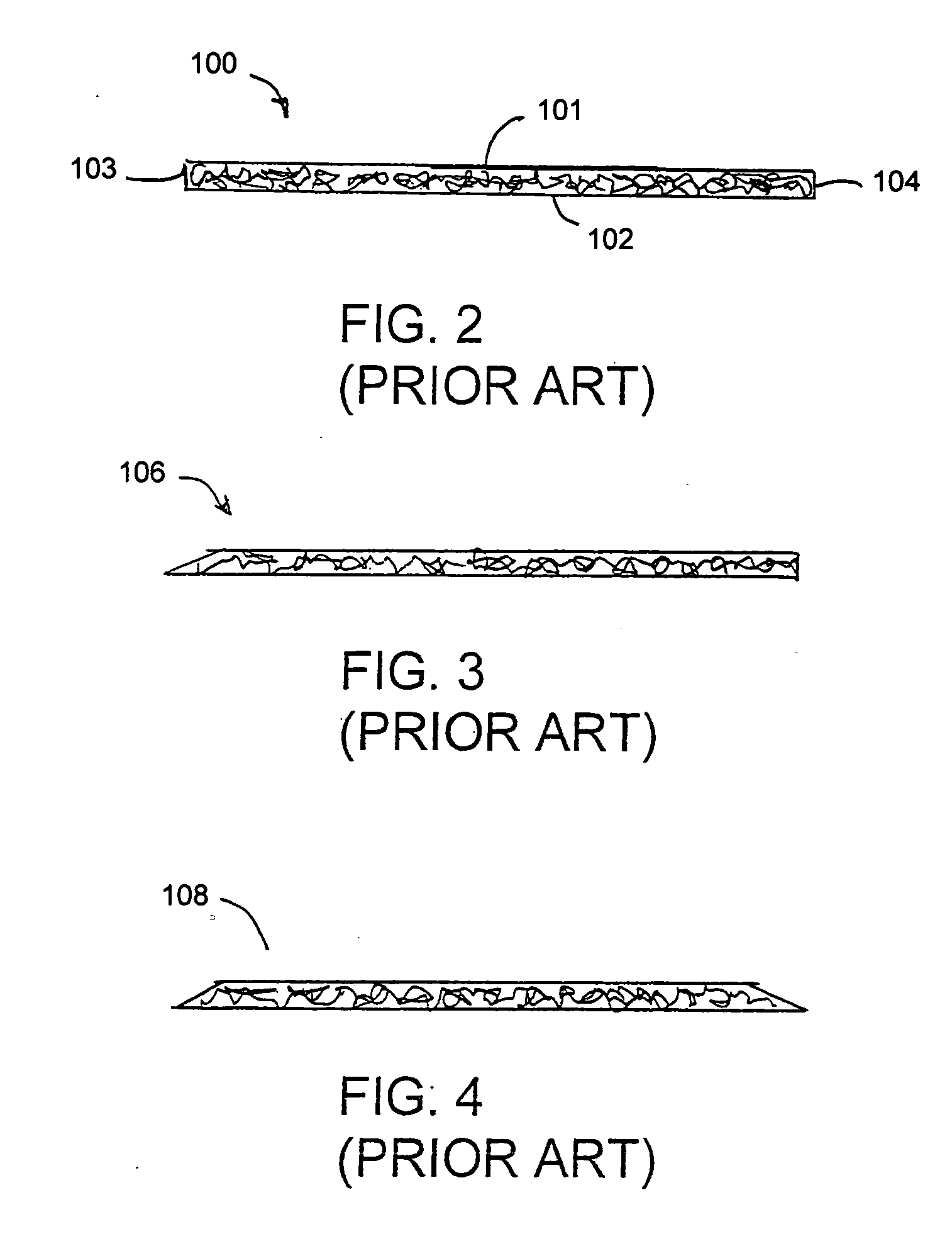
[0018] The formation of the specified profile on the blanks of sheet material requires some movement or flowing of the sheet material as part of the forming process. The
cutting and forming of the blank of the sheet material can be carried out more easily if the sheet material is sufficiently warm to permit flowing of the sheet material in response to forces exerted by the forming and
cutting die. Thus, the forming and cutting step of the process preferably is carried out before the sheet material is cured completely. Alternatively, the sheet material may be heated prior to forming and cutting to ensure that the sheet material can be formed without excessive pressure.
[0020] The process and apparatus of the invention eliminates the labor intensive skiving operations associated with the prior art. Hence, the stiffeners such as
heel counters or box toes can be formed easily with a high degree of
automation at the location at which the sheet material is formed. The profiled stiffeners then can be shipped to the site for manufacturing the finished product without the need to transport waste portions of the web to the site of manufacturing and then to transport waste portions of the web back to its origin for recycling. Hence, the subject invention results in very substantial reductions in shipping costs, and corresponding reductions in overall costs. For example, waste of the web may be ground up or otherwise processed at the site of the web production. Particles derived from the waste of the web may be heated or otherwise processed to achieve proper
moisture content and then may be re-deposited directly back into the extruder.
[0021] The process and apparatus of the invention achieves many other manufacturing efficiencies. For example, prior art processes typically require complicated and costly compounding of powders for
coating onto a fabric web. Those process steps are entirely unnecessary with preferred embodiments of the subject invention. Prior art processes also often require mixing of hot melts for application to a fabric web. The costs and time associated with mixing and applying the
hot melt coating is avoided with preferred embodiments of the subject invention. Processes that involve saturating a fabric web also require large ovens for
drying the fabric web. The ovens take up a substantial amount of floor space in a manufacturing facility and require significant amounts of energy to operate. In contrast, preferred embodiments of the subject process and apparatus may rely largely upon the heat imparted to the web as part of the
extrusion process. Any reheating that may be required to soften the web prior to forming and cutting is less than the heat required for
drying the saturated web. Hence, heaters used with the apparatus of the subject invention are preferably smaller and more energy efficient. Still further, the subject invention avoids the sheeting that is an integral part of prior art processes. In particular, the prior art webs are
cut into rectangular sheets for shipment to a separate manufacturing facility. The sheets then are fed sequentially into a
stamping apparatus. In contrast, the subject invention enables finished products to be formed and
cut substantially simultaneously and directly from the web. The separate sheeting process is not required. Recycling also is much more efficient. Unused parts of the web can be recycled directly into the hopper of the extruder. Prior art processes typically must include a
cryogenic grinding process or some other complex
grinding process for the
waste material.
[0022] An alternate apparatus and method in accordance with the invention avoids the initial formation and / or use of sheet material prior to making the profiled blanks. In this regard, the apparatus may include first and second rolls defining a nip therebetween. The first roll may have a smooth outer surface. The second roll, however, is formed with an array of inwardly directed die recesses corresponding to the specified shapes of the profiled blanks. Areas between their respective die recesses are disposed to substantially contact the smooth outer surface of the first roll at the nip between the first and second rolls. The apparatus of this embodiment is employed by depositing a flowable resin at the leading side of the nip between the rolls. Rotation of the rolls forces the resin into the die recesses in the second roll and hence forms the resin material into shapes corresponding to the specified profile for the blanks. Further rotation of the rolls moves the profiled blanks away from the nip and enables the blanks to be separated from the second roll and transported to an appropriate location for
quality control, packaging and shipment to a customer.
[0023] The alternate apparatus may further include a
retainer disposed in the interstice at the downstream side of the nip. The
retainer has a shape substantially conforming to the shape of the interstice and functions to keep the flowable resin in the die recesses while the resin is curing sufficiently to be separated from the die recesses of the second roll. A specified flowability and curing can be achieved at appropriate times during the process by heating the first roll and / or by cooling the second roll and the
retainer. The heating of the first roll helps to maintain flowability of the resin as the resin approaches the upstream side of the nip. The cooling of the second roll and the cooling of the retainer helps to cure the resin after the resin has been urged into the respective die recesses.
[0024] The apparatus and method of the alternate embodiment described above achieves all of the advantages of the first embodiment. However, the alternate embodiment offers still further advantages. In particular, the process of the alternate embodiment avoids the need and expense for an extruder that first forms a web of material. Rather, the resin is fed directly into the nip between the first and second rollers. Second, the alternate embodiment produces virtually no waste that would otherwise require recycling. In contrast, the first embodiment and the above-described prior art yield significant amounts of waste at locations on the web between the blanks that are
cut according to the prior art process or roll formed according to the first embodiment.


