
Continuous methods of making fiber reinforced concrete panels

a technology of fiber reinforced concrete and continuous methods, which is applied in the direction of manufacturing tools, transportation and packaging, rotary stirring mixers, etc., can solve the problems of fiber lumping and balling during the mixing operation, the viscosity of cementitous mixtures for extruding, and the inability to meet the requirements of use, so as to facilitate the formation of fiber reinforced concrete panel products, and eliminate the need for time-consuming and expensive panel finishing

Active Publication Date: 2022-01-18
UNITED STATES GYPSUM CO
View PDF132 Cites 2 Cited by
  • Summary
  • Abstract
  • Description
  • Claims
  • Application Information

AI Technical Summary

Benefits of technology

The patent text describes a new method for making fiber reinforced concrete products using a continuous process. This method involves blending reinforcing fibers with the rest of the cementitous components in a continuous operation to create a smooth and flowable mixture. The resulting mixture can then be easily worked on a continuous production line to create the final product shape. The technique also allows for uniform thickness across the entire product, resulting in a more consistent and quality finished product.

Problems solved by technology

Cementitous mixtures for extruding are very viscous and not suitable for uses such as shotcrete or deposition through a forming assembly on a cementitous panel production line.
Some major limitations and drawbacks of the current state-of-the art concrete mixers and mixing technologies for producing fiber reinforced cementitous slurry mixtures include:
The mixing operation in a batch mixer is not continuous thus making their use more difficult in applications where a continuous supply of slurry is needed such as in the case of a continuous panel production line.
Since a large amount of fibers are added at a time in a batch mixer, that leads to fiber lumping and balling during the mixing operation.
Longer mixing times involved with the batch mixing process tend to damage and break the reinforcing fibers.
Batch mixers are not very useful and practical with respect to handling rapid setting cementitous materials.

Method used


Image

  • Continuous methods of making fiber reinforced concrete panels
  • Continuous methods of making fiber reinforced concrete panels
  • Continuous methods of making fiber reinforced concrete panels

Examples


example 1

[0507]FIG. 39 shows a photograph of a slump patty 101 of a fiber reinforced cementitious slurry mixture made using the method of the present invention employing a slurry mixer followed by a separate fiber-slurry mixer.

example 2

[0508]FIG. 40 is a thickness profile of a ¾″ thick panel of fiber reinforced cement produced by the method of the present invention employing a slurry mixer followed by a separate fiber-slurry mixer. It shows consistent thickness achieved when a single layer was deposited. The fiber-slurry mixture contained Portland cement, gypsum, and glass fibers.


PUM

PropertyMeasurementUnit
thickaaaaaaaaaa
particle densityaaaaaaaaaa
median diameteraaaaaaaaaa

Abstract

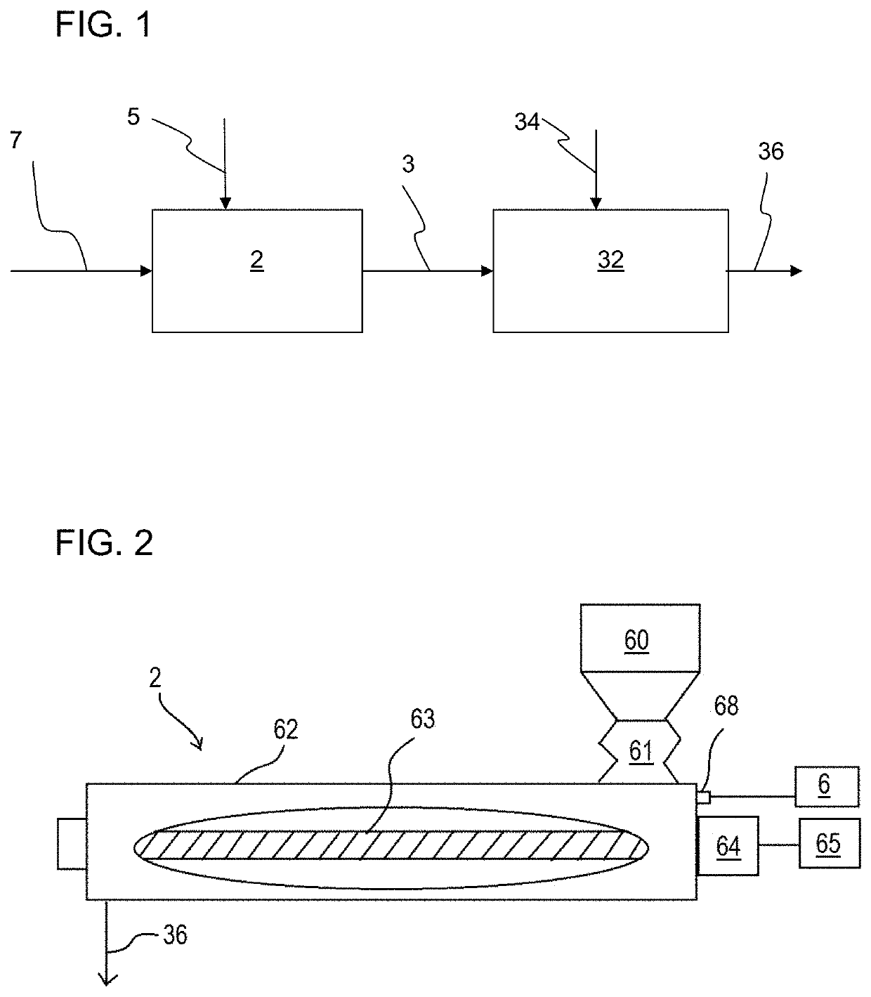
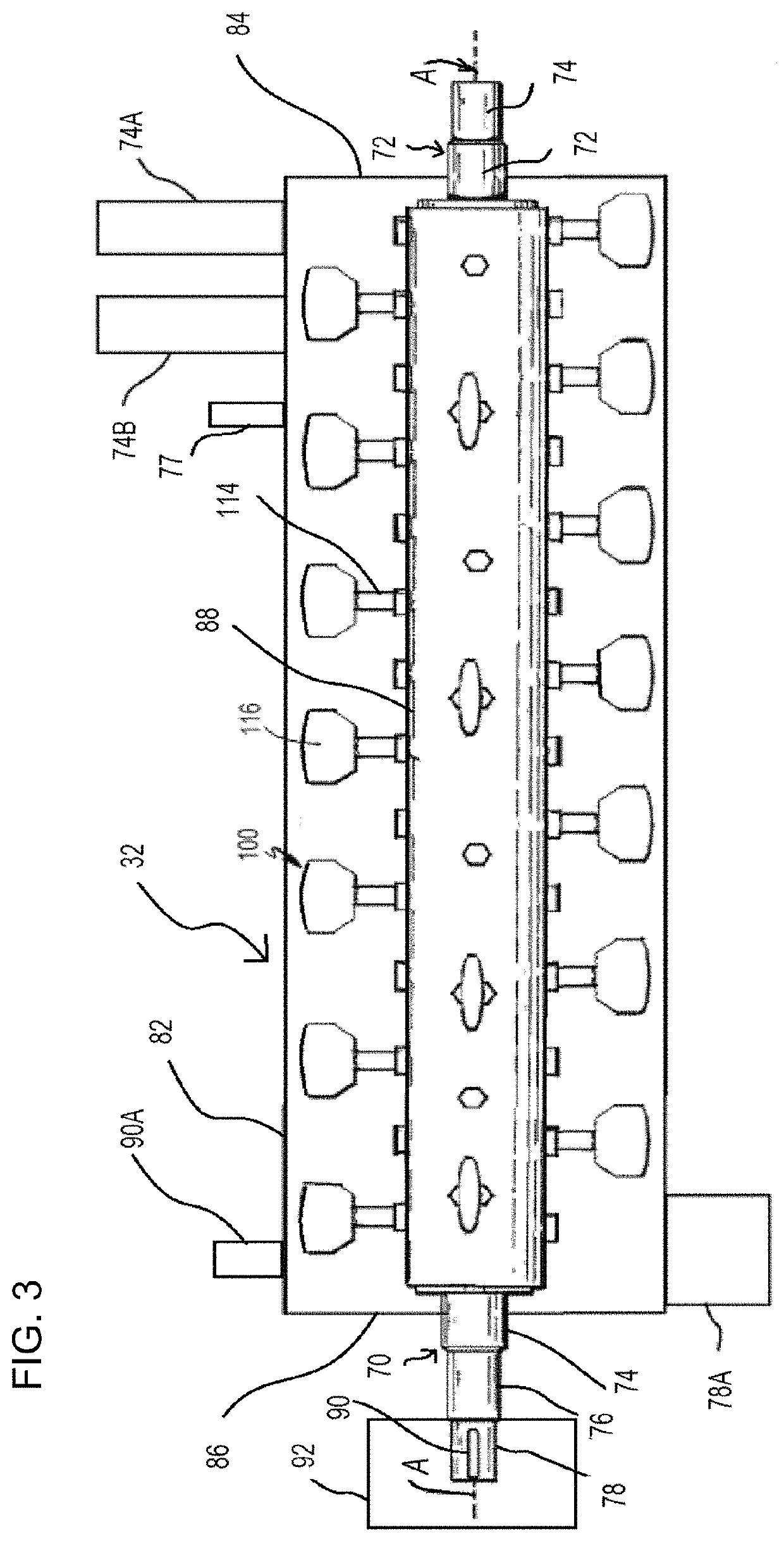
Continuous method including mixing water and cementitous powder to form slurry; mixing the slurry and reinforcement fibers in a single pass horizontal continuous mixer to form fiber-slurry mixture, the mixer including an elongated mixing chamber having a reinforcement fiber inlet port, and upstream of the fiber inlet port is an inlet port to introduce water and cementitous powder together as one stream or at least two inlet ports to introduce water and dry cementitous powder separately as separate streams into the chamber, a rotating horizontal shaft / s within the chamber, part of the chamber for mixing the fibers and slurry and moving the fiber-slurry mixture to a mixture outlet; discharging the fiber-slurry mixture from the mixer outlet; forming and setting the fiber-slurry mixture on a moving surface; cutting the set mixture into fiber reinforced concrete panels and removing the panels from the moving surface.

Description

CROSS REFERENCE TO RELATED APPLICATIONS[0001]This application is related to:U.S. Provisional Patent Application No. 62 / 371,578, entitled CONTINUOUS MIXER AND METHOD OF MIXING REINFORCED FIBERS WITH CEMENTITOUS MATERIALS, filed Aug. 5, 2016;[0002]U.S. Provisional Patent Application No. 62 / 371,569, entitled HEADBOX AND FORMING STATION FOR FIBER REINFORCED CEMENTITOUS PANEL PRODUCTION, filed Aug. 5, 2016;[0003]U.S. Provisional Patent Application No. 62 / 371,590, entitled A METHOD FOR PRODUCING FIBER REINFORCED CEMENTITIOUS SLURRY USING A MULTI-STAGE CONTINUOUS MIXER, filed Aug. 5, 2016;[0004]all herein incorporated by reference in their entirety.[0005]This application claims the benefit of U.S. Provisional Patent Application No. 62 / 371,554 entitled CONTINUOUS METHODS OF MAKING FIBER REINFORCED CONCRETE PANELS, filed Aug. 5, 2016 incorporated by reference in its entirety.FIELD OF THE INVENTION[0006]This invention discloses a method of producing fiber reinforced cementitous materials in a...

Claims


Application Information

Patent Timeline
Patent Type & Authority Patents(United States)
IPC IPC(8): B28C7/04B28C5/40B28C5/12B28B5/02B28B3/22B01F7/00B01F7/08B28C5/14B01F7/04B29B7/48B28B1/52B29B7/90B29C48/67B29B7/72B29B7/44B01F3/12B28B13/02B01F15/02B01F3/20B05C1/08
CPCB28C7/0418B01F3/1221B01F7/0065B01F7/00708B01F7/042B01F7/085B28B1/522B28B1/526B28B3/224B28B5/027B28B13/0275B28C5/1238B28C5/1246B28C5/1284B28C5/143B28C5/146B28C5/148B28C5/402B29B7/44B29B7/482B29B7/483B29B7/488B29B7/72B29B7/90B29C48/67B01F3/2042B01F7/048B01F2015/0221B05C1/0834B01F23/53B01F27/2123B01F27/1921B01F27/702B01F27/723B01F35/715B01F23/706B01F27/707B01F27/73
Inventor DUBEY, ASHISHGROZA, PETER B.NELSON, CHRISTOPHER R.
Owner UNITED STATES GYPSUM CO
Learn More