
Optical sight (variants)

An optical aiming and cube technology, applied in the field of optical sights, can solve the problems of indistinguishable, not allowing shooters to shoot, etc., and achieve the effect of precise aiming

Inactive Publication Date: 2013-04-10
RUSOPTICALSYST
View PDF5 Cites 7 Cited by
  • Summary
  • Abstract
  • Description
  • Claims
  • Application Information

AI Technical Summary

Problems solved by technology

[0005] However, in low light or in dim weather, the black aiming reticle is practically indistinguishable from the background of the gray image of the target (e.g., an image of a wild boar), which does not allow the shooter to make accurate shooting

Method used


Image

  • Optical sight (variants)
  • Optical sight (variants)
  • Optical sight (variants)

Examples


Embodiment Construction
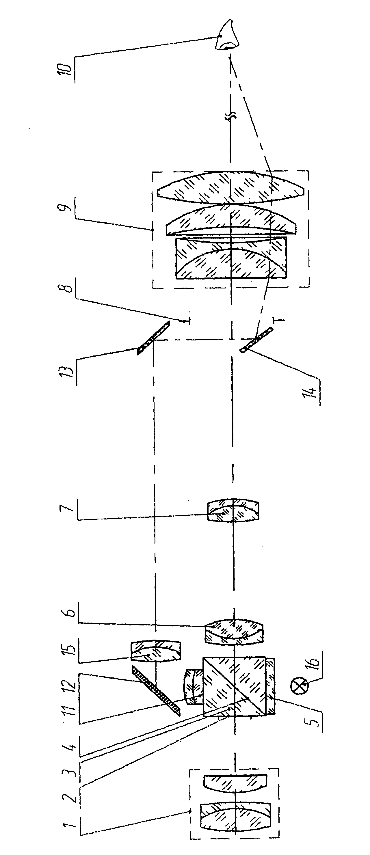
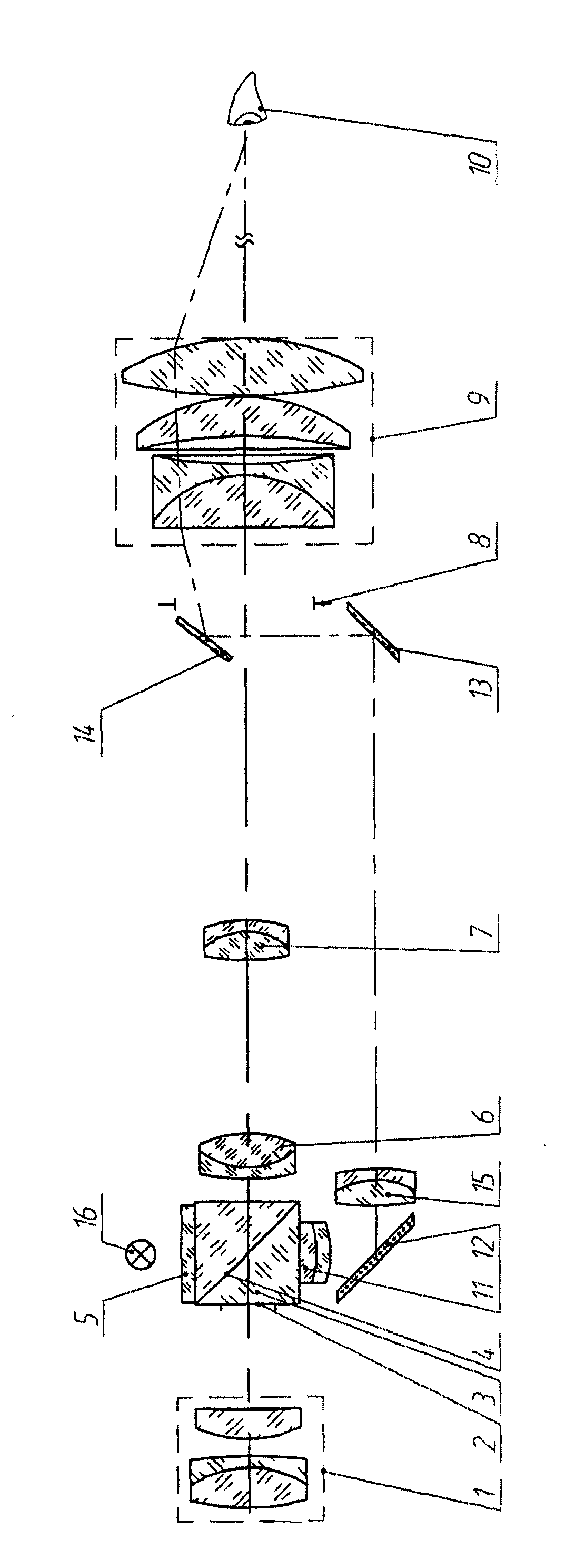
[0020] Variant 1

[0021] This variant of the optical sight is in the figure 1 , the figure shows sequentially on the same axis: objective lens 1; There is a beam-splitting surface 4, on the lower surface of which beam-splitting cube is placed an illuminated reticle 5 made transparent with respect to an opaque background; and a first positive part 6 of the positive imaging system ; The second positive component 7 of the positive image system; the focal plane 8 of the eyepiece 9 ; and the shooter's eye 10 . The third positive part 11 is glued on the upper plane of the cube 3; the first plane mirror 12 is arranged on the third positive part 11, parallel to the beam splitting surface 4 of the cube 3; the second plane mirror 13 is arranged perpendicular to the first plane mirror. The third plane mirror 14 is arranged obliquely to the optical axis, with its reflective surface facing the eyepiece 9, between the focal plane 8 of the eyepiece 9 and the second part 7 of the erecting...


PUM


Abstract

The invention relates to optical instrumentation, more specifically to optical sights used in the firing of small arms. The technical result achieved through the realization of the different embodiments of the sight is a more accurate aim at indistinct targets at dusk and in overcast conditions.; This result is achieved in that in the sight, which comprises the following, arranged consecutively: an objective, a reticle, an erector assembly consisting of a first and a second positive component, each of which is comprised of two cemented lenses, and an eyepiece, as well as a beam splitter cube, the beam splitting surface of which is in the form of a diagonal plane, three mirrors and a third positive component comprised of two cemented lenses, wherein the first flat mirror, which is parallel to the beam splitting surface of the cube, is situated on the same axis as the third positive component, the second flat mirror is perpendicular to the first mirror in front of the focal plane of the eyepiece, and the third mirror, which is inclined to the optical axis and has its reflecting surface oriented towards the eyepiece, is situated between the focal plane of the eyepiece and the second component of the erector assembly; the cube is situated in front of the erector assembly, the front face of the cube, to which a first reticle is applied, is situated in the focal plane of the objective, and a fourth positive component is situated on the axis between the first and second mirrors.

Description

technical field [0001] The invention relates to the optics-manufacturing industry, that is to say to optical sights for small arms shooting. Background technique [0002] At present, there is an optical sight of the patent RU 2364899 published on August 20, 2009. The optical sight includes, arranged in sequence: an objective lens; a positive image system composed of first and second positive components ( erecting system), the first and second positive components are each formed by cementing two lenses; and an eyepiece. A beam-splitting cube, whose beam-splitting planes are formed as diagonal surfaces, is arranged between the first and second components of the erector imaging system. A third additional positive part cemented by two lenses is arranged above the cube, a first plane mirror parallel to the surface of the beam-splitting cube is positioned on the same axis as the third positive part, after which, A second plane mirror in front of the focal plane of the eyepiece i...

Claims


Application Information

Patent Timeline
Patent Type & Authority Applications(China)
IPC IPC(8): G02B27/34F41G1/34
CPCG02B27/34F41G1/345F41G1/38G02B23/00G02B23/10
Inventor P·A·布拉格夫E·V·茨维勒夫
Owner RUSOPTICALSYST
Features
  • Generate Ideas
  • Intellectual Property
  • Life Sciences
  • Materials
  • Tech Scout
  • Unparalleled Data Quality
  • Higher Quality Content
  • 60% Fewer Hallucinations
Learn More