
A tubular belt conveyor

A technology for tubular belts and conveyors, which is applied in the direction of conveyors, conveyor objects, transportation and packaging, etc. It can solve the unnatural and poor stress conditions of tubular belt hoops, special personnel are required to patrol and watch, and the tubular belt has high resistance to depression and other problems, to achieve the effect of small resistance, simple structure and low manufacturing cost

Active Publication Date: 2016-12-28
裴志胜
View PDF7 Cites 0 Cited by
  • Summary
  • Abstract
  • Description
  • Claims
  • Application Information

AI Technical Summary

Problems solved by technology

[0002] The tubular belt conveyor was invented by the Japanese in the 1980s. The core technology of this invention is a device such as "composing a tubular belt conveying cabin with a plurality of linear idlers" (see Figure 9 , Patent No. 87104332.7), but the most troublesome thing is this device, the device method is primitive, the structure is cumbersome, it is difficult to manufacture and install, and the force condition of the tubular band hoop in this transmission cabin is extremely unnatural and unreasonable. The indentation resistance of the tubular belt is large, and the reliability is poor. Special personnel are required to patrol and watch over it. If you are not careful, it will cause a twisted belt jam or broken belt accident. The manufacturing, installation, use and maintenance costs are very high, which is a waste of money. Although the This technology has entered the public domain, but the adverse consequences caused by its congenital deficiencies cannot be expressed in a few words; Figure 10 , Patent No. 200620030280.1), since the idea ignores the existence of twisted straps and tape torn edges, it is a thankless disservice

Method used


Image

  • A tubular belt conveyor
  • A tubular belt conveyor
  • A tubular belt conveyor

Examples


Embodiment Construction

[0033] Below in conjunction with accompanying drawing, the present invention and concrete implementation will be further described:

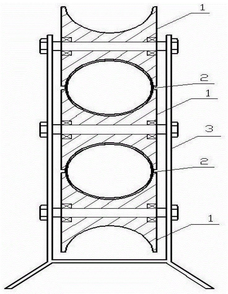
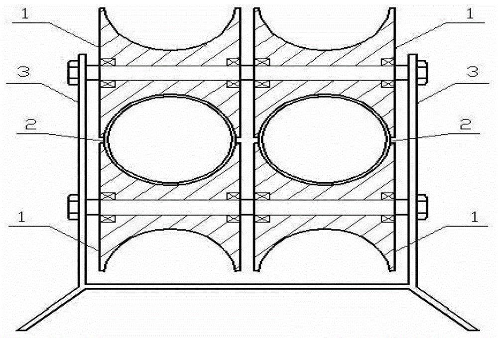
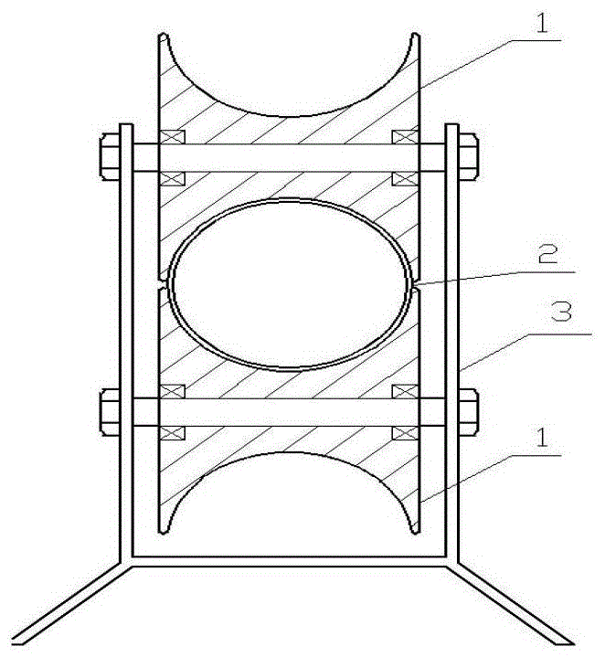
[0034] see figure 1 , a concave-curved idler 1 and an open idler bracket 3 are designed. The idler 1 is arranged and installed on the idler bracket 3 through the idler shaft in an up-middle-down manner. The bearing section of the tubular belt The upper and lower transmission channels are respectively hooped in the upper and lower transmission channels composed of three idlers 1, and the upper and lower transmission channels share the intermediate idler 1. The cross-sectional shape of the transmission channel is determined by the concave arc on the idler 1. Yes, this concave arc is comprehensively considered according to the straightness of the transmission route. For example, when there are frequent turns in the horizontal direction, the cross-sectional shape of the transmission channel should preferably be a vertical ellipse, and for example, ...


PUM


Abstract

A novel tubular belt conveyor comprises a tubular belt, a power traction, a roller a roller frame, and an opening and closing way for the tubular belt, and is characterized in that the rollers (1) with concave curvature are disposed on the open type roller frame (3), a carrying segment and a return segment of the tubular belt are respectively circle hooped in an upper and a lower transmission channels which comprise the rollers or are respectively circle hooped in a left transmission channel and a right transmission channel which are connected with each other or independent from each other; each of the rollers (1) can be composed by a plurality of rolling wheels; the cross-sectional shape of the transmission channels can be various; and a roller shaft can be sleeved with two or a plurality of rollers (1), so that two sets of or a plurality sets of transmission lines are realized. The novel tubular belt conveyor is ingenious in design, natural in method, reasonable in structure, flexible in application, superior in performance, low in cost, and easy in operation, and accordingly is an ideal tubular belt conveyor.

Description

technical field [0001] The invention relates to a tubular belt conveyor, which belongs to the field of conveying machinery. Background technique [0002] The tubular belt conveyor was invented by the Japanese in the 1980s. The core technology of this invention is a device such as "composing a tubular belt conveying cabin with a plurality of linear idlers" (see Figure 9 , Patent No. 87104332.7), but the most troublesome thing is this device, the device method is primitive, the structure is cumbersome, it is difficult to manufacture and install, and the force condition of the tubular band hoop in this transmission cabin is extremely unnatural and unreasonable. The indentation resistance of the tubular belt is large, and the reliability is poor. Special personnel are required to patrol and watch over it. If you are not careful, it will cause a twisted belt jam or broken belt accident. The manufacturing, installation, use and maintenance costs are very high, which is a waste of ...

Claims


Application Information

Patent Timeline
Patent Type & Authority Patents(China)
IPC IPC(8): B65G15/08B65G39/12
Inventor 裴志胜裴春光
Owner 裴志胜
Learn More