Anti-slide pile with I-shaped cross section

A technology of anti-sliding piles and cross-sections, which is applied in sheet pile walls, foundation structure engineering, excavation, etc., can solve the problems of large concrete pouring volume and high cost, and achieve the effects of construction safety, small construction section and cost reduction

Inactive Publication Date: 2013-04-17
CHINA UNIV OF GEOSCIENCES (WUHAN)
View PDF2 Cites 1 Cited by
  • Summary
  • Abstract
  • Description
  • Claims
  • Application Information

AI Technical Summary

Problems solved by technology

[0005] The purpose of the present invention is to solve the problem of large amount of concrete pouring and high cost of existing anti-slide piles, and provide a reinforced concrete anti-slide pile with an I-shaped cross-section that has good mechanical performance and can reduce costs. Sliding pile

Method used


Image

  • Anti-slide pile with I-shaped cross section
  • Anti-slide pile with I-shaped cross section
  • Anti-slide pile with I-shaped cross section

Examples


Embodiment 1

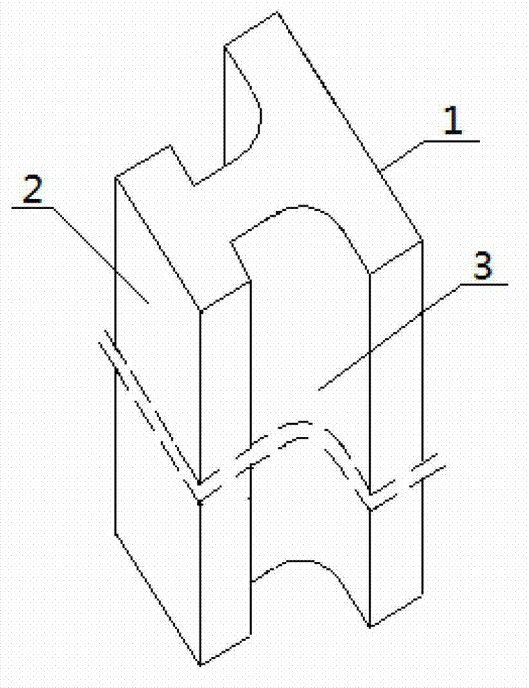
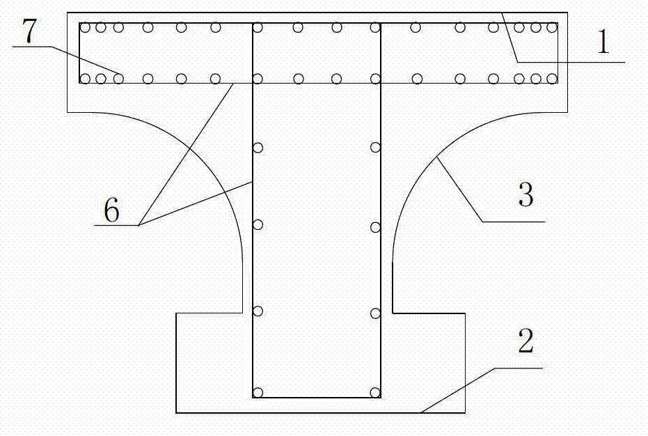
[0024] Embodiment 1: the anti-sliding pile 8 of a kind of I-shaped cross section provided by the present invention, its structure is as follows figure 1 As shown, it is formed by pouring reinforced concrete. The cross-section of the poured reinforced concrete anti-slide pile is I-shaped, the upper end of the I-shaped is the pile rear end 1, the lower end of the I-shaped is the pile front end 2, and the pile rear end 1 The lateral width is longer than that of the pile front end 2, and an arc-shaped body part 3 is formed between the pile rear end 1 and the pile front end 2.

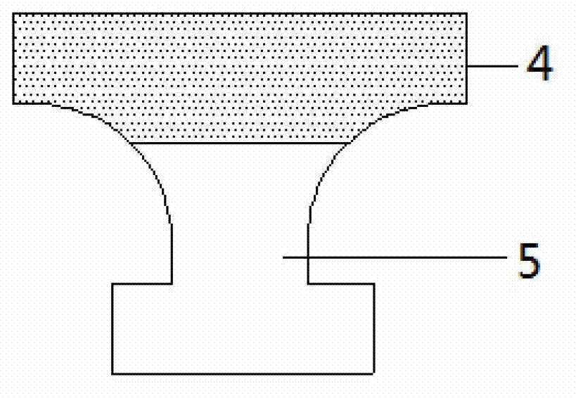
[0025] The stress distribution on the anti-slide pile cross section of the present invention is as follows: figure 2 As shown, the force on the rear end 1 of the anti-sliding pile is tensile stress, which belongs to the tension zone 4, and the force on the front end 2 of the pile and the front part of the arc body part 3 is mostly compressive stress, which belongs to the compression zone 5. In the reinfor...

Embodiment 2

[0029] Embodiment 2: Apply the anti-slide pile 8 of a kind of I-shaped cross-section that the embodiment of the present invention 1 provides to carry out construction, in the construction process of this anti-slide pile, because the engineering quantity of each pile is not big, the landslide body in construction little impact on stability. The construction section of the anti-slide pile is small, and the construction can be carried out by means of mechanical construction. The specific construction steps are as follows:

[0030] (1) Level the site, and measure and locate the center point of the anti-slide pile according to the design drawings. The distance between the centers of adjacent anti-slide piles is slightly larger than that of conventional rectangular anti-slide piles.

[0031] (2) Equipment in place, including digging equipment such as excavators, bulldozers, rock drills, safety equipment such as helmets, seat belts, and software, wall protection equipment such as fo...


PUM


Abstract

The invention relates to an anti-slide pile with an I-shaped cross section. The anti-slide pile with the I-shaped cross section is poured by reinforced concrete. Transverse width at the rear end of the anti-slide pile is larger than that of a common anti-slide pile with a rectangular cross section, so that post-pile soil arch effects are brought into full play, pile center distance between two adjacent anti-slide pile can be increased when the anti-slide piles are disposed on a plane, and the amount of the required anti-slide piles is reduced under the same landslide conditions to reduce cost. The rear end and the front end of the anti-slide pile are arc-shaped, stress concentration damaging the anti-slide pile is prevented from being generated at tips. The anti-slide pile can bear large slope pushing force has good bending resistance. The cross section area of the anti-slide pile is remarkably smaller that of the anti-slide pile with the rectangular cross section, so that concrete quantity and rebar quantity needed are reduced greatly, a large amount of concrete and rebar is saved, and cost is lowered. The anti-slide pile is small in construction section and simple and safe in construction, has promising popularization application prospect and facilitates mechanical construction.

Description

technical field [0001] The invention relates to a reinforced concrete anti-slide pile for slope engineering and landslide treatment engineering, in particular to an anti-slide pile with an I-shaped cross section, which belongs to the technical field of slope or slope stabilization. Background technique [0002] There are many ways to control slopes and landslides, among which setting anti-slide piles is a very widely used control scheme. The anti-slide principle of anti-slide piles is to drive the anti-slide piles below the sliding surface, and transmit the thrust of the slope body on the upper part to the lateral soil or rock mass below the piles through the pile body, relying on the lateral resistance of the lower part of the piles to bear The downward thrust of the slope or sliding body keeps the slope or landslide in balance or stability. [0003] In today's landslide and slope treatment projects, a single anti-slide pile has limited anti-slide ability compared to the e...

Claims


Application Information

Patent Timeline
Patent Type & Authority Applications(China)
IPC IPC(8): E02D5/34E02D5/36E02D17/20
Inventor 李长冬廖伟代先尧雍睿梁德明王姣刘庆涛
Owner CHINA UNIV OF GEOSCIENCES (WUHAN)
Why Eureka
Try Eureka