Check patentability & draft patents in minutes with Patsnap Eureka AI!

Light guide column, light emitting structure and illumination device employing the same

A light-emitting structure and lighting device technology, applied in lighting devices, lighting and heating equipment, light guides of lighting systems, etc., can solve problems such as increasing the lighting angle and uneven brightness distribution

Inactive Publication Date: 2013-04-17
LEXTAR ELECTRONICS CORP
View PDF5 Cites 5 Cited by
  • Summary
  • Abstract
  • Description
  • Claims
  • Application Information

AI Technical Summary

Problems solved by technology

[0004] The object of the present invention is to provide a light guide column and a light-emitting structure and lighting device using the light guide column, so as to increase the light-emitting angle and solve the problem of uneven brightness distribution

Method used


Image

  • Light guide column, light emitting structure and illumination device employing the same
  • Light guide column, light emitting structure and illumination device employing the same
  • Light guide column, light emitting structure and illumination device employing the same

Examples


no. 1 example

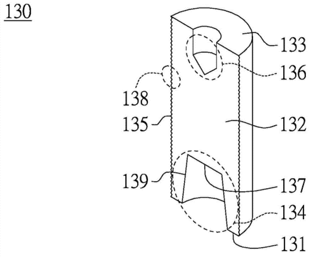
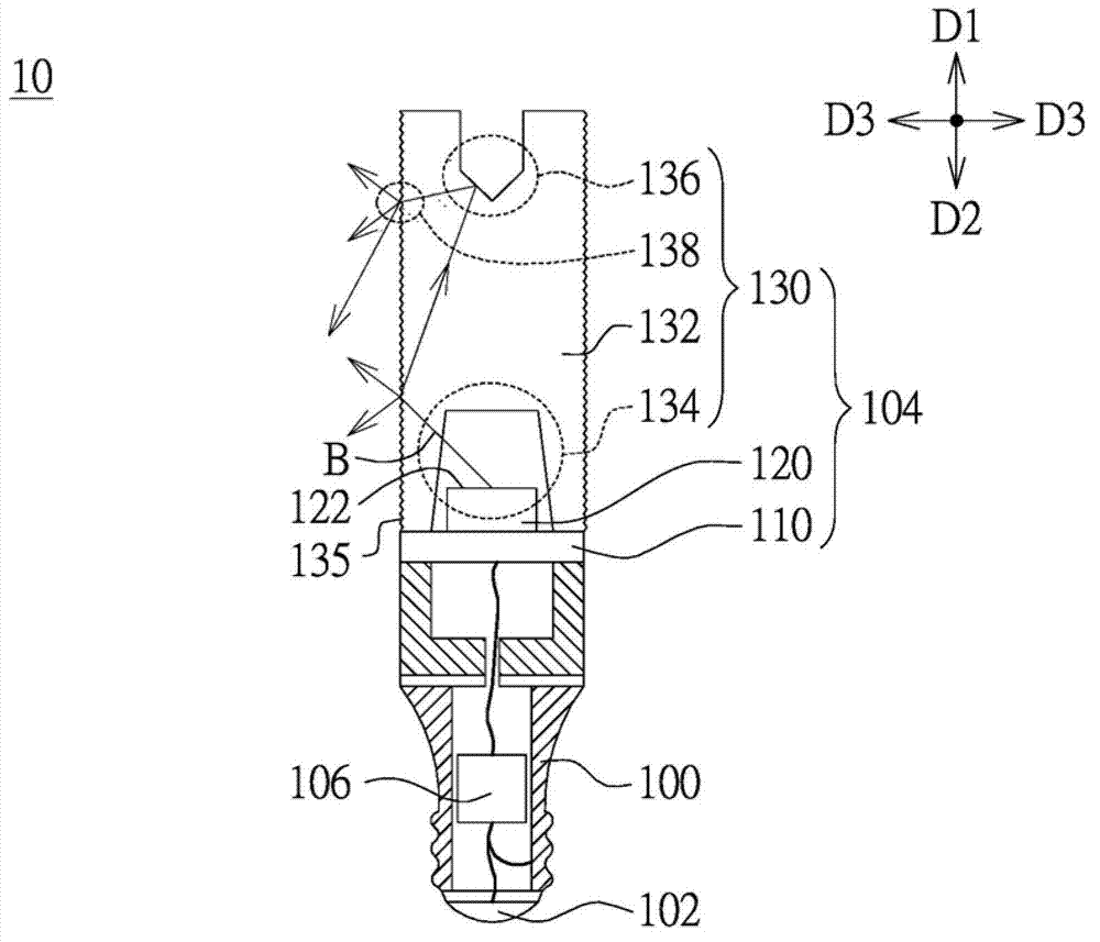
[0051] Please refer to figure 1 and figure 2 ,in figure 1 A schematic cross-sectional view of the light guide column 130 according to an embodiment of the present invention is shown, figure 2 A schematic diagram of the light emitting structure 104 and the lighting device 10 using a single light guide bar 130 is shown. The lighting device 10 includes a lamp holder 100 , an electrical connector 102 and a light emitting structure 104 . The lamp holder 100 has an accommodating space for setting a driving circuit module 106 , and the electrical connector 102 is located under the lamp holder 100 for receiving external power. The lamp holder 100 can be made of metal (such as copper or aluminum) or insulating and heat-dissipating material (such as plastic or ceramics). In this embodiment, the driving circuit module 106 can perform voltage transformation and AC / DC conversion, and the circuit board 110 is electrically connected to the electrical connector 102 through the driving c...

no. 2 example

[0056] Please refer to Figure 5 , which shows a schematic diagram of the light emitting structure 204 and the lighting device 20 using multiple rows of light guide rods 230 . The difference between this embodiment and the first embodiment is that the light emitting structure 204 and the illuminating device 20 include multiple rows of light guide columns 230 and multiple light emitting sources 220 . Each light guide column 230 is disposed on the circuit board 210 and correspondingly located above the light emitting source 220 for adjusting the light emitting angle of each light emitting source 220 . The driving circuit module 206 is connected to each light emitting source 220 via the circuit board 210 to control the light emitting sources 220 individually or simultaneously. The light emitting source 220 is, for example, a light emitting diode. Part of the light can be reflected by the reflective structure 236 to emit light toward the side surface 235 of the light guide body 2...


PUM


Abstract

The invention discloses a light guide column, a light emitting structure employing the light guide column and an illumination device. A light guide column is disposed on the top of a light source. The light guide column includes a column body, a cavity, a reflection structure and a micro-structure. The column body has a first end and a second end opposite to the first end. The cavity on the first end is for gathering the light source. The reflection structure is on the second end, when light emitted from the light source, a portion of the light reflected by the reflection structure to emit toward a lateral surface of the column body and others transmitted to the front side direction. The micro-structure is formed on the lateral surface of the column body can facilitate the emitting light from the column body uniformly.

Description

technical field [0001] The invention relates to a lamp, and in particular to a light guide column, a light-emitting structure and a lighting device using the light guide column. Background technique [0002] Generally speaking, light-emitting diodes are used as light sources and can be used in different lamp structures, such as bulb lamps or lamp tubes, to provide required lighting. The light emitted by the light-emitting diode is projected outward from the lampshade of the bulb lamp or the lamp tube to form a light field in the front direction, but the light-emitting angle thereof is less than 180 degrees. Therefore, compared with the traditional incandescent light source, the incandescent light source has a 360-degree light emitting angle, which is larger than that of the LED light source. [0003] In addition, when the brightness distribution is uneven, there will be dark lines (mura) on the side of the lampshade. Therefore, the uniformity and distribution range of the ...

Claims


Application Information

Patent Timeline
IPC IPC(8): F21V8/00G02B6/00F21Y101/02
Inventor 黄亮翔周士钦段生杏
Owner LEXTAR ELECTRONICS CORP
Features
  • R&D
  • Intellectual Property
  • Life Sciences
  • Materials
  • Tech Scout
  • Unparalleled Data Quality
  • Higher Quality Content
  • 60% Fewer Hallucinations
Learn More