
Anti-collapse device for horizontal flue in front of dust collector in thermal power plant

A technology of horizontal flue and dust collector, applied in exhaust gas device, combustion product treatment, combustion method, etc., can solve the problems of flue collapse, flue overload prevention requirements, and identification of flue dust load, etc. The effect of avoiding the collapse of the flue

Active Publication Date: 2015-12-23
STATE NUCLEAR ELECTRIC POWER PLANNING DESIGN & RES INST CO LTD
View PDF6 Cites 0 Cited by
  • Summary
  • Abstract
  • Description
  • Claims
  • Application Information

AI Technical Summary

Problems solved by technology

[0003] At present, in the relevant national design and maintenance specifications, there are no clear prevention regulations for the mixture of dust and water in the flue, which leads to the overload of the flue. Identify whether the dust load of the flue is abnormal. Once the dust and water are mixed and the load exceeds the design allowable value, the flue collapse accident will occur

Method used


Image

  • Anti-collapse device for horizontal flue in front of dust collector in thermal power plant
  • Anti-collapse device for horizontal flue in front of dust collector in thermal power plant
  • Anti-collapse device for horizontal flue in front of dust collector in thermal power plant

Examples


Embodiment 1

[0034] see Figure 5 As shown, one side of the bottom of the main body elbow 2-1 is provided with a magnet 2-4, and the other side is provided with a hinge 2-5, and the plug 2-2 is connected to the main body elbow 2-1 through the hinge 2-5. Movably connected together, the magnet 2-4 and the metal plug 2-2 are connected together by magnetic attraction; the magnetic attraction of the magnet 2-4 and the plug 2-2 is greater than that of the main body elbow 2-1 plus the main body The weight of dry ash filled with dry ash in elbow 2-1 is less than the weight of wet ash filled with wet ash in main elbow 2-1. The weight of plug 2-2 is the absolute value of the negative pressure of the flue multiplied by the main elbow 2-1 bottom circular cross-sectional area.

Embodiment 2

[0036] see Image 6As shown, the bottom side of the main body elbow 2-1 is provided with a spring top plate 2-9, the plug 2-2 is movably connected with the main body elbow 2-1 through the rotating shaft 2-7, and the pressing The lower end of the spring 2-8 is connected to the plug 2-2, and the upper end is connected to the spring top plate 2-9. The rigidity range of the compression spring 2-8 is greater than the weight of dry ash filled with dry ash in the main body elbow 2-1 , but less than the weight of wet ash filled with wet ash in the main body elbow 2-1; the weight of the bottom plug 2-2 is the absolute value of the negative pressure of the flue multiplied by the circular cross-sectional area at the bottom of the main body elbow 2-1.

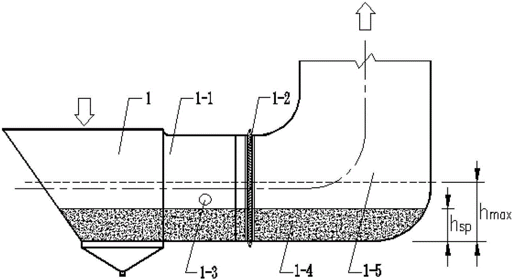
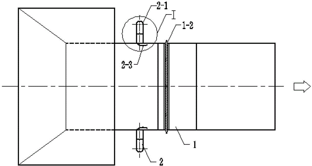
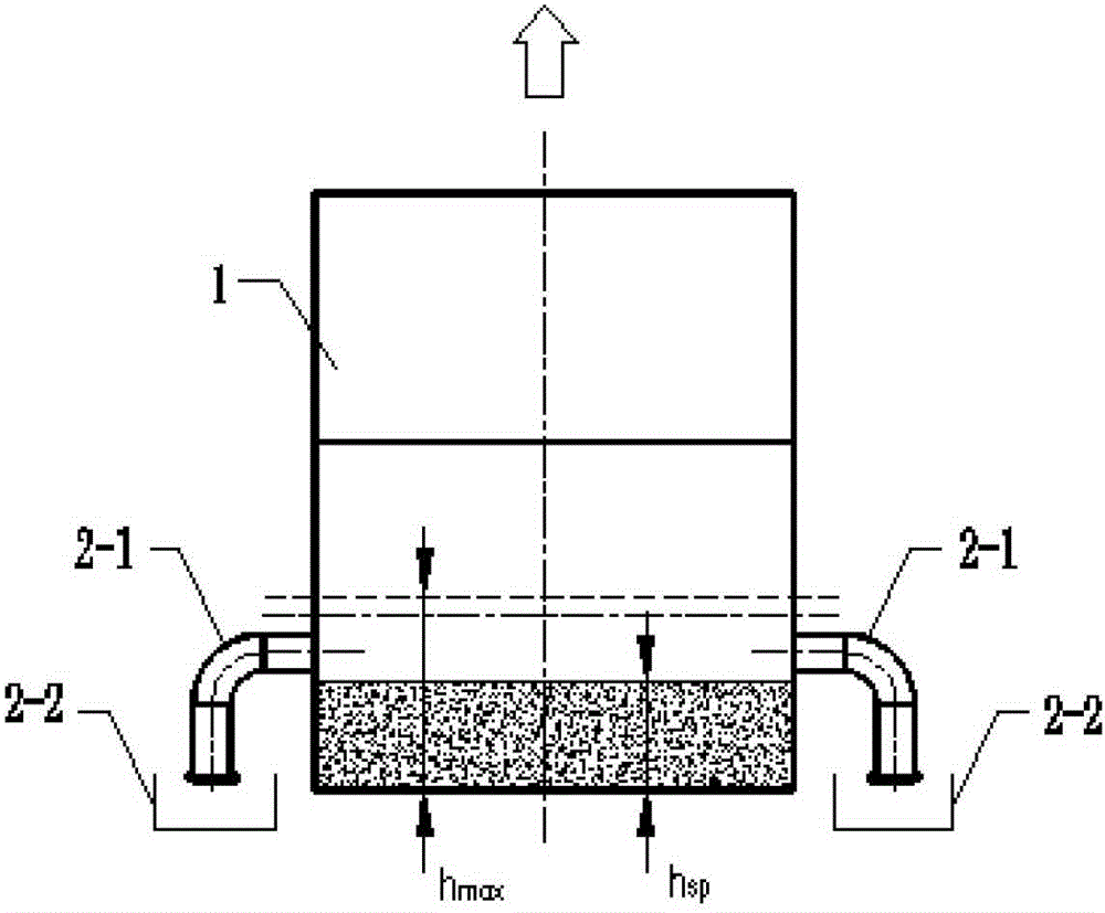
[0037] The working principle of the embodiment of the present invention: due to the possibility of local uneven height due to ash accumulation, an anti-collapse device 2 is installed on both sides of the flue. Due to the diffusion effect, ...


PUM


Abstract

The invention discloses a front horizontal flue collapse prevention device of a thermal power plant deduster and belongs to the thermal power plant dedusting field. The front horizontal flue at least comprises a horizontal flue wall, an expansion joint, an inner cavity of a flue and a vertical flue wall, wherein the horizontal flue wall is connected with the vertical flue wall through the expansion joint, mounting holes for a collapse prevention device are formed on bilateral sides of the horizontal flue wall, and the mounting holes are provided with the collapse prevention device. According to the collapse prevention device arranged on the front horizontal flue of a deduster since mixture of dust stratification and water is easy to produce on the front horizontal flue of the deduster, the mixture of the dust stratification and the water inside the flue can be automatically cleared before the flue dust stratification load is over limit bearing load to avoid flue collapse accidents caused by the abnormal load of the mixture of the dust stratification and the water in the front horizontal flue and flue collapse accidents can be effectively avoided due to the facts that the water accumulation in the flue can be found particularly and excessive water accumulation and dust stratification can be discharged before serious accidents occur.

Description

technical field [0001] The invention relates to the field of dust removal in thermal power plants, in particular to an anti-collapse device for a horizontal flue in front of a dust collector in a thermal power plant. Background technique [0002] At present, the horizontal flue in front of the precipitator of all coal-fired thermal power plants will have a certain degree of ash accumulation. It will cause ash to mix with water, resulting in a greatly increased ash load in the flue. When the leaked moisture accumulates to a certain extent and the ash load of the flue exceeds the limit load of the flue support structure, an accident of flue collapse will occur at this time, resulting in loss of life and property. In the past ten years, there have been many flue collapse accidents. [0003] At present, in the relevant national design and maintenance specifications, there is no clear prevention regulation for the mixture of dust and water in the flue, which leads to the overlo...

Claims


Application Information

Patent Timeline
Patent Type & Authority Patents(China)
IPC IPC(8): F23J13/00
Inventor 张桂英邵杰席学章
Owner STATE NUCLEAR ELECTRIC POWER PLANNING DESIGN & RES INST CO LTD
Learn More