Projection device

A technology for projection devices and projection screens, which is applied in projection devices, optics, instruments, etc., can solve the problems of the projection lens being unable to image, the optical characteristics of the film being removed, and achieve the effects of stable imaging, low cost, and low expansion coefficient

Active Publication Date: 2013-04-17
QISDA OPTRONICS (SUZHOU) CO LTD +1
View PDF4 Cites 4 Cited by
  • Summary
  • Abstract
  • Description
  • Claims
  • Application Information

AI Technical Summary

Problems solved by technology

However, the aspheric lens made of plastic has a high expansion coefficient, so it is prone to film release or optical property changes under high temperature changes, making the projection lens unable to maintain stable imaging under high temperature changes

Method used


Image

  • Projection device
  • Projection device
  • Projection device

Examples


Embodiment Construction

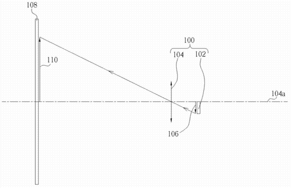
[0024] Please refer to figure 1 , figure 1 It is a schematic diagram of the projection device of the present invention. Such as figure 1 As shown, the projection device 100 includes a light valve (light valve) 102 and a non-telecentric projection lens 104 , and the projection device 100 is used for projecting an image 106 onto a projection screen 108 . Wherein, the light valve 102 has a plurality of pixel units for providing an image 106, that is, the image 106 is generated at the position of the light valve 102, and the light valve 102 can be a reflective display panel or a digital micro-mirror element (digital micro-mirror device). mirror device, DMD), but not limited to this. For example, the projection device 100 can irradiate the light beam on the light valve 102 through the light source and the illumination lens, and reflect part of the light beam through the micromirror element on the light valve 102, so that the reflected light beam has an image 106, but the present...


PUM


Abstract

The invention relates to a projection device which is used for projecting images onto a projection screen; the projection device comprises a light valve for providing the images and a non-telecentric projection lens for projecting the images. The non-telecentric projection lens comprises a plurality of spherical lenses which comprise a first lens group and a second lens group. The first lens group is arranged between the light valve and the projection screen, has negative refractive index, and comprises a first meniscus lens. The second lens group is arranged between the first lens group and the light valve, has positive refractive index, and comprises a second meniscus lens. According to the projection device, only the spherical lenses are used, so that the projection device is light in weight, thin in thickness, small in size and lower in production cost. Because glass has a smaller expansion coefficient compared with plastics, stripping or the changes of optical properties caused by the impact of temperature changes can be prevented, so that the impact of the temperature changes on the projection device is reduced, and stable imaging can be maintained under high temperature changes.

Description

technical field [0001] The invention relates to a projection device, in particular to a projection device using a non-telecentric projection lens of a spherical lens. Background technique [0002] With the rapid development of technology, projection devices have gradually played an indispensable role in family, entertainment or business purposes. A traditional projection device is composed of a light valve and a projection lens. The light valve is used to generate an image, which is magnified by the projection lens and projected onto a projection screen. [0003] Generally, projection devices can be divided into telecentric projection devices and non-telecentric projection devices. Since the chief ray of the non-telecentric projection device is not parallel to the optical axis, the chief ray enters the zoom projection lens at an angle, so the projected image can be shifted upward on the projection screen to meet the requirement. In a traditional non-telecentric projection ...

Claims


Application Information

Patent Timeline
Patent Type & Authority Applications(China)
IPC IPC(8): G03B21/14G02B13/00G02B1/00
Inventor 林明坤吴宗训
Owner QISDA OPTRONICS (SUZHOU) CO LTD
Why Eureka
Try Eureka