
Portable Test Board

A test board and portable technology, applied in the field of optical communication, can solve the problems of inconvenient production and portability, complex peripheral equipment, low reliability, etc., and achieve the effects of easy portability, improved test efficiency and low price

Active Publication Date: 2016-04-20
WUHAN TELECOMM DEVICES
View PDF4 Cites 0 Cited by
  • Summary
  • Abstract
  • Description
  • Claims
  • Application Information

AI Technical Summary

Problems solved by technology

[0005] It can be seen that when the existing test board is used for on-site commissioning of the optical module, there are disadvantages such as complex peripheral equipment, low reliability, and inconvenient production and portability.

Method used


Image

  • Portable Test Board

Examples


Embodiment Construction

[0021] The present invention will be further described below in conjunction with the accompanying drawings and specific embodiments, so that those skilled in the art can better understand the present invention and implement it, but the examples given are not intended to limit the present invention.

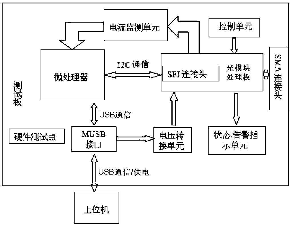
[0022] Such as figure 1 As shown, it is a functional block diagram of an embodiment of the portable test board of the present invention, including a circuit board, a microprocessor is arranged in the middle of the circuit board, an MUSB interface is provided at the front end of the circuit board, and the microprocessor It is electrically connected with an MUSB (Miniature Universal Serial Bus, miniature universal serial bus) interface, and the microprocessor is also electrically connected with an optical module processing board.

[0023] The optical module processing board is provided with an SFI (scalableframerinterface, high-speed electrical interface) connector. The interpretati...


PUM


Abstract

The invention discloses a portable test board, which comprises a circuit board. A microprocessor is arranged in the middle of the circuit board. An MUSB (Micro Universal Serial Bus) interface is arranged at the front end of the circuit board. The microprocessor is electrically connected with the MUSB interface. The microprocessor is additionally and electrically connected with an optical module processing board. The MUSB interface is additionally and electrically connected with the optical module processing board. The optical module processing board is additionally and electrically connected with an SMA (Small A Type) connector. The portable test board can be connected with an upper computer through a USB (Universal Serial Bus) interface, not only can the power supply to an optical module be realized, but also the communication between the optical module and the upper computer is realized, the portable test board simultaneously has a state alarming and indicating function, the working current of the optical module can also be monitored without additionally increasing test instruments, the equipment required for testing the optical module is reduced, the testing cost is reduced and the testing efficiency is improved.

Description

technical field [0001] The invention relates to the field of optical communication, in particular to a portable test board capable of testing optical modules. Background technique [0002] With the development of optical communication network transmission capacity, there is an increasing demand for miniaturized optical modules, which requires the production of smaller optical modules to reduce production costs and provide higher access density. Finally meet the user access capacity requirements. [0003] At present, the test boards used in the industry often require the simultaneous support of external communication conversion equipment and external power supply when performing on-site debugging of miniaturized and packaged optical modules, which increases the test cost and complexity. [0004] Optical modules in miniaturized packages generally use a +3.3V regulated DC power supply to power them, and the power consumption is generally less than 2W. At the same time, the co...

Claims


Application Information

Patent Timeline
Patent Type & Authority Patents(China)
IPC IPC(8): H04B10/07
Inventor 汪颖陈龙张柳煜
Owner WUHAN TELECOMM DEVICES
Learn More