
Molding tool with a three dimensional surface relief pattern and method of making the same

A technology of surface relief and three-dimensional surface, which is applied in the field of molds with three-dimensional surface relief patterns and their production, and can solve problems such as deformation

Inactive Publication Date: 2013-04-17
TAIWAN GREEN POINT ENTERPRISE
View PDF9 Cites 8 Cited by
  • Summary
  • Abstract
  • Description
  • Claims
  • Application Information

AI Technical Summary

Problems solved by technology

[0006] The object of the present invention is to provide a mold with a three-dimensional surface relief pattern and a manufacturing method thereof, which can overcome the above-mentioned defects that the surface relief pattern is deformed or damaged due to softening, stretching and shrinkage, and can form a horizontal A curved corner spanning a non-planar surface of a molded article

Method used


Image

  • Molding tool with a three dimensional surface relief pattern and method of making the same
  • Molding tool with a three dimensional surface relief pattern and method of making the same
  • Molding tool with a three dimensional surface relief pattern and method of making the same

Examples


Embodiment Construction

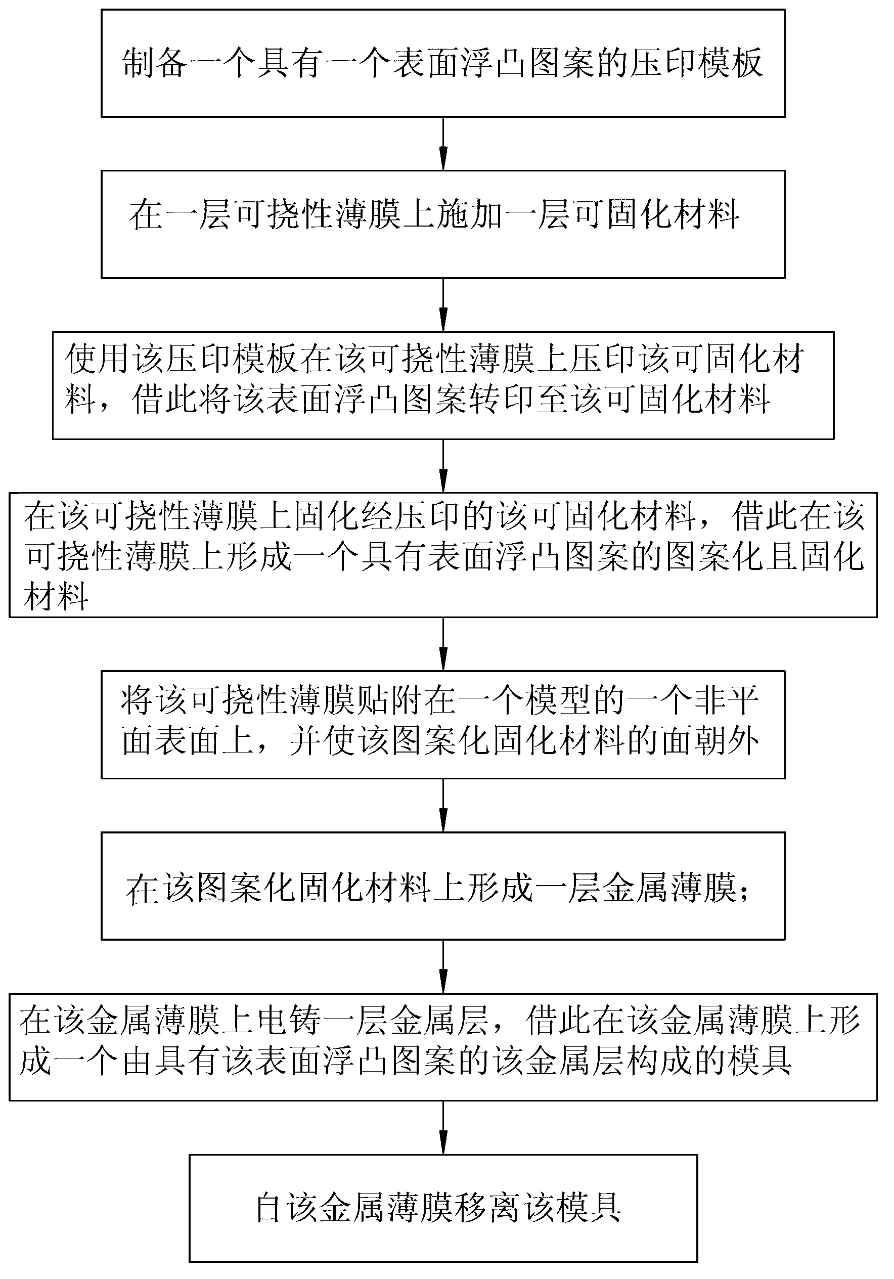
[0015] figure 1 and Figures 2A to 2K Means making a light-diffractive surface relief pattern with a three-dimensional surface relief pattern, such as a holographic pattern, or a pattern with a plurality of microstructures, each microstructure defined herein as having a micron size or nanometer The successive steps of the first preferred embodiment of the method of mold 29 are used for the production of a three-dimensional molded article (not shown), such as a mobile phone case having the three-dimensional embossed surface pattern.

[0016] The method of the first preferred embodiment comprises: forming a photoresist material 22 on a substrate 21 made of a metal plate (see Figure 2A ); use a photomask 23 and form a surface relief pattern (see Figures 2A to 2B ); electroforming a metal layer on the patterned photoresist material 22, thereby forming an imprint template 24 with the surface relief pattern on the patterned photoresist material 22 (see Figure 2C ); remove the ...


PUM

PropertyMeasurementUnit
thicknessaaaaaaaaaa

Abstract

A method of making a molding tool includes: preparing an imprinting master having a surface relief pattern; applying a curable material on a flexible film; embossing the curable material on the flexible film using the imprinting master so as to transfer the surface relief pattern to the curable material; curing the embossed curable material so as to form a patterned-and-cured material; attaching and conforming the flexible film to a non-planar surface of a model; forming a thin metal film over the patterned-and-cured material; electroforming a metal layer over the thin metal film so as to form a molding tool of the metal layer; and removing the molding tool from the thin metal film.

Description

technical field [0001] The invention relates to a mold with a three-dimensional surface relief pattern and a manufacturing method thereof. Background technique [0002] In recent years, in order to attract customers' attention, many molded articles, such as cosmetic cases, mobile phone casings, and casings of handheld electronic devices, etc., are expected to have holographic patterns, light-diffractive surface embossments, etc. formed on the outer surface. patterns (or other microstructured patterns), and / or logos. [0003] US Pat. No. 5,071,597 discloses a method for mass producing molded articles having holographic patterns or microstructure patterns formed on non-planar surfaces. The method comprises the steps of: preparing a photosensitive plate having a substrate and a photoresist formed on the substrate; optically forming a surface relief hologram or pattern on the photoresist; electroforming forming a metal template conforming to the pattern of the surface relief p...

Claims


Application Information

Patent Timeline
Patent Type & Authority Applications(China)
IPC IPC(8): B29C59/02B29C33/42
CPCB29C33/3857B29C33/424B29C59/02
Inventor 王肖璞张世宗蔡瑞龙陈东泉谢佩珊张惠媚
Owner TAIWAN GREEN POINT ENTERPRISE
Learn More