Net and line cutter

Active Publication Date: 2009-09-01
SPURS MARINE MFG
View PDF11 Cites 5 Cited by
  • Summary
  • Abstract
  • Description
  • Claims
  • Application Information

AI Technical Summary

Benefits of technology

[0003]It is accordingly an object of the invention to provide improvements to the prior art rotary weed and line cutter to overcome the problems encountered in long term use of the device. It is an object of the invention to overcome the deformation of the elastomeric segment. It is an object of the invention to

Problems solved by technology

When the rope guard is welded back in place, it is difficult to reposition the non-rotating blade support so that the non-rotating blade is pa

Method used


Image

  • Net and line cutter
  • Net and line cutter
  • Net and line cutter

Examples


Embodiment Construction

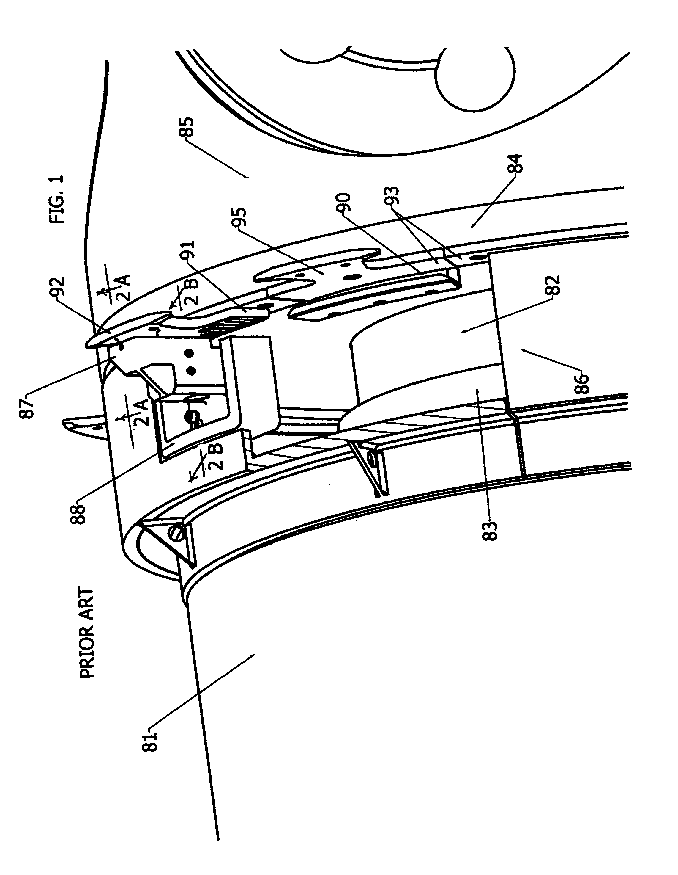
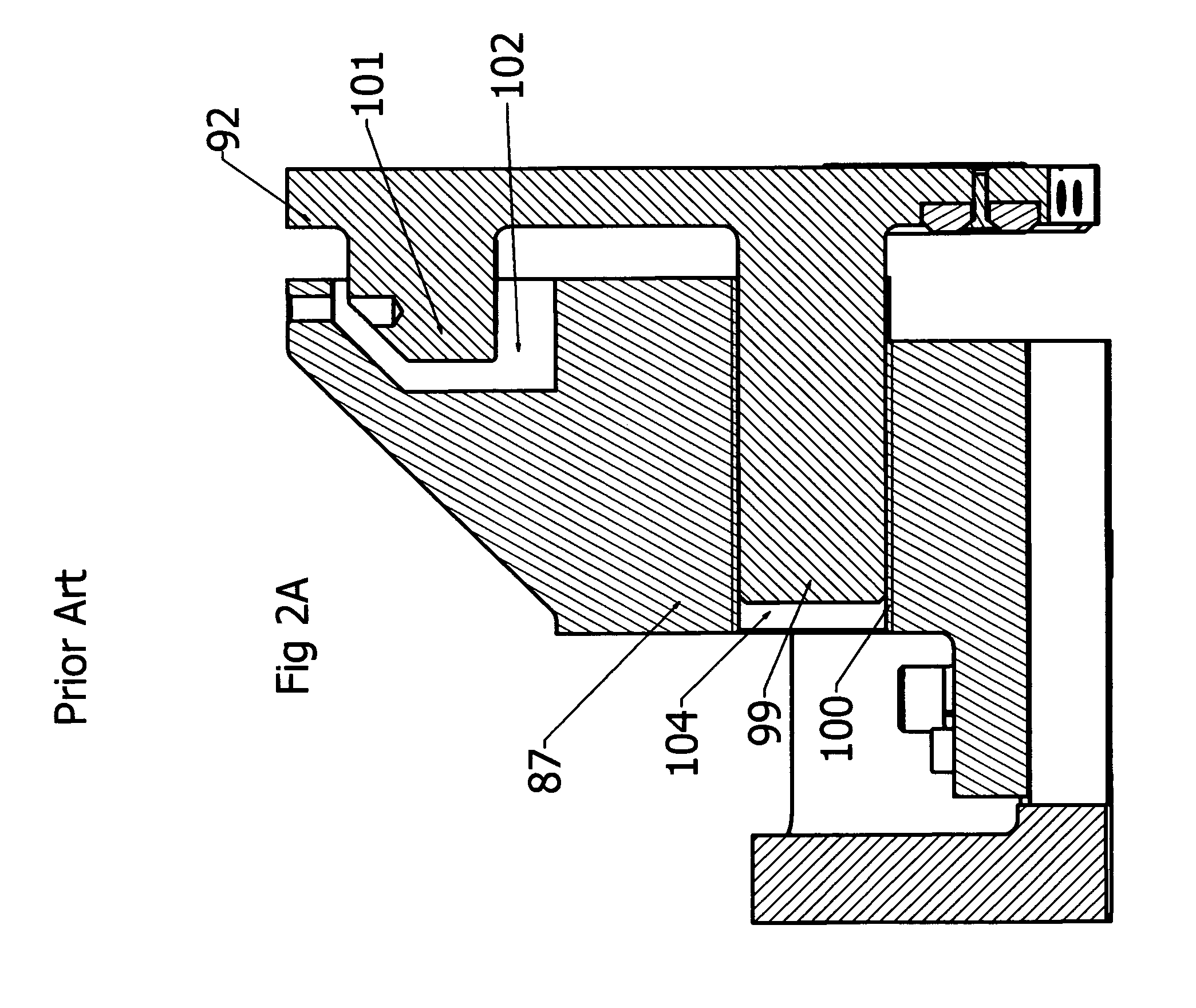
[0016]Referring now first to description of the prior art in FIGS. 1, 2A and 2B, a vessel 81 has a propeller shaft 82 journalled within a propeller shaft housing 83 with a propeller hub 84 carrying propeller 85 affixed to the shaft. A rotating blade assembly 93 is affixed to the shaft or propeller hub. A rope guard 86 surrounds the shaft and is fixed to the vessel. A support block 87 for supporting the non-rotating blade 92 is bolted to the rope guard 86 in correct position for cooperating with the rotating blade assembly 93. The support block 87 is bolted by bolts to support member 88 that is welded to the rope guard. The support member is held to correct non-rotating blade position relative to the rotating blade assembly 93 and then welded to the rope guard 86. During dry dock maintenance operations, the rope guard may be cut off in order to access the shaft bearing and / or seal. To weld it back in correct position is a difficult task. The rotary blade assembly 93 is bolted to the ...


PUM


Abstract

Apparatus shears foreign matter that might entangle propellers and related structures on a moving vessel by action of a blade rotating with the propeller that cooperates with a non-rotating blade held close to the rotating blade. The mechanisms for holding the blades close and parallel include a lubricant packed passage for a supporting cylinder portion of the non-rotating blade, enclosed clamping elastic bias elements for controlled movement of the cylinder, and adjustments for holding the blade parallel.

Description

FIELD OF THE INVENTION[0001]This invention relates generally to marine devices that cut lines, weeds, nets, and the like, and more particularly to shearing cutters that employ a blade rotating with the propeller of a vessel that cooperates with a non-rotating blade mounted on a non-rotating portion of a vessel adjacent the propeller shaft to engage and shear items that appear between the two cutters. Lines, nets, weeds and the like are commonly encountered by vessels. They may be swept by the propeller blades into the propeller shaft apparatus i.e. into the space where the propeller shaft extends from its housing where they can cause great harm. There they may cut through the oil seals causing loss of lubricant. The current trend toward long line fishing wherein heavy monofilament nylon many miles long is lying in the water has exacerbated the problem.DESCRIPTION OF RELATED ART[0002]U.S. Pat. No. 6,004,174 issued Dec. 21, 1999 to applicant discloses a rotating blade that rotates wit...

Claims


Application Information

Patent Timeline
IPC IPC(8): B63H1/28
CPCB63H5/165
Inventor GOVAN, DONALD T.
Owner SPURS MARINE MFG
Why Eureka
Try Eureka