Antennas and Antenna Control Systems
An antenna control and antenna technology, which is applied to antennas, individually powered antenna arrays, electrical components, etc., and can solve problems that have not yet been realized.
- Summary
- Abstract
- Description
- Claims
- Application Information
AI Technical Summary
Problems solved by technology
Method used
Image
Examples
Embodiment 1
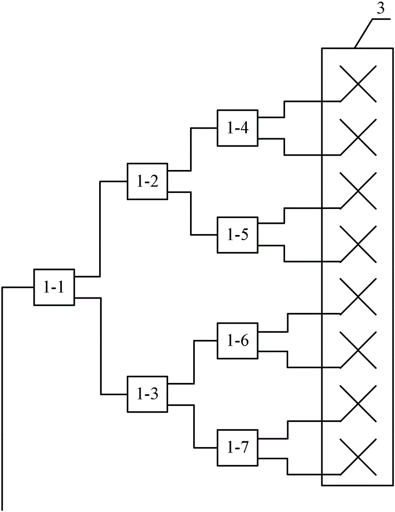
[0021] Such as figure 1 As shown, the antenna provided by the embodiment of the present invention includes a hierarchical beam characteristic control structure and a radiation unit 3; the hierarchical beam characteristic control structure includes a beam characteristic control device 1-1 at the top layer, and at least two beam characteristic control devices at the bottom layer Control devices 1-4 to 1-7; each beam characteristic control device has an input end and two output ends; wherein, the input end of the beam characteristic control device on the top layer is used to receive signals, and the two output ends directly or indirectly The received signals are assigned to the input ends of at least two bottom beam characteristic control devices, and at least two bottom beam characteristic control devices redistribute the respective assigned signals and then output them to the radiation from their corresponding output ports. Unit 3.
[0022] The beam characteristic control devi...
Embodiment 2
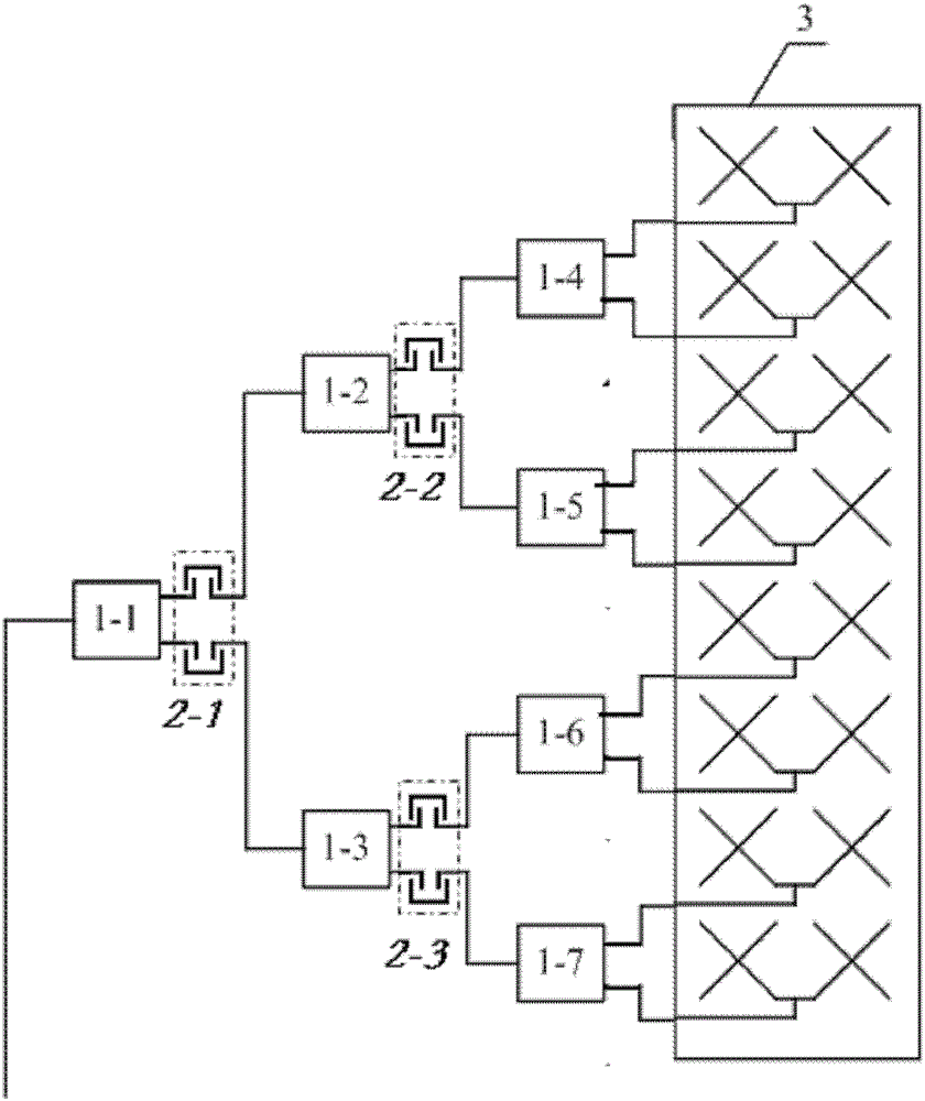
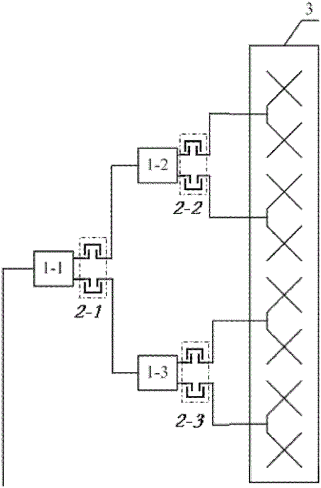
[0025] This embodiment is basically the same as Embodiment 1, the difference is: as figure 2 As shown, each output terminal of the bottom beam characteristic control devices 1 - 4 to 1 - 7 is connected to a plurality of radiation units 3 . As a preferred solution, the radiation units 3 on each output end are arranged vertically. For the antenna with multiple radiation units 3, using one output to control multiple radiation units 3 can simplify the structure of the antenna, and can also achieve different lobe widths between 0° and 70°, such as 3°, 6°, 10° °, 12°, 33°, 45°, 60°, etc. Of course, the radiating elements on each output terminal can also be arranged horizontally, such as image 3 shown; or arranged diagonally at an angle.
[0026] In the embodiment of the present invention, at least one beam characteristic control device is provided with a phase control device on an output end or an input end. As a preferred solution, phase control devices 2-1 to 2-3 are provide...
Embodiment 3
[0030] This embodiment is basically the same as Embodiment 2, except that the beam characteristic control device 1 is composed of a power divider, a phase shifter and an electric bridge 13; the power divider and the phase shifter are integrated designs, and the phase shifter Both outputs are connected to the bridge 13 .
[0031] Specifically, the structure of the power divider and phase shifter can be as follows Image 6 As shown, the signal line is connected to a rotating shaft 14, and the phase of the two signals is changed by rotating the pointer of the rotating shaft 14 on the arc 15; the structure of the power divider and the phase shifter can also be as follows Figure 7 As shown, a slidable medium 16 is set on the transmission line of the power division part, and the electrical length of the two channels is changed by sliding the medium 16, thereby changing the phase of the two signals.
[0032] The common point of the above two implementations is that the phases of th...
PUM
 Abstract
Description
Claims
Application Information
 - R&D Engineer
- R&D Manager
- IP Professional
- Industry Leading Data Capabilities
- Powerful AI technology
- Patent DNA Extraction
Browse by: Latest US Patents, China's latest patents, Technical Efficacy Thesaurus, Application Domain, Technology Topic, Popular Technical Reports.
© 2024 PatSnap. All rights reserved.Legal|Privacy policy|Modern Slavery Act Transparency Statement|Sitemap|About US| Contact US: help@patsnap.com


