Cylindrical single-grinding grinder

A cylindrical refiner technology, applied in the field of pulp and paper making, can solve the problems of unsatisfactory refining quality and refining efficiency, inconvenient installation, maintenance and operation, uneven refining quality, etc. , to achieve the effects of reduced length and volume, increased effective power, and stable refining performance

Inactive Publication Date: 2015-01-07
SUZHOU FEIYU PRECISION TECH
View PDF10 Cites 0 Cited by
  • Summary
  • Abstract
  • Description
  • Claims
  • Application Information

AI Technical Summary

Problems solved by technology

[0002] At present, the widely used refiners in the field of pulp and papermaking include double-disc refiners and conical refiners, but these two types of equipment have shortcomings: (1). In the pulping zone, the pulp flows in the direction of the centrifugal force, and the linear velocity of the refining zone changes from small to large from the center to the outer circle, which will lead to uneven refining quality; (2), in the conical refiner In the refining area, due to the taper of the grinding disc, the direction of the pulp flow is constantly changing with the component force of the centrifugal force. The closer the taper is to 90°, the closer the pulp flow direction is to the direction of the centrifugal force. The disk refiner has improved to a certain extent, but it still cannot achieve satisfactory results. In addition, the working stability of the conical refiner is also a major problem that is bothering people.
[0006] In addition, the existing refiners are large in size, inconvenient for installation, maintenance and operation, and the supporting power is large, which leads to serious energy waste in some small-scale production
[0007] To sum up, the refining quality and refining efficiency of existing refiners are not satisfactory, and a refiner with better performance and outstanding economic benefits is needed

Method used


Image

  • Cylindrical single-grinding grinder

Examples


Embodiment Construction

[0028] The present invention will be specifically introduced below in conjunction with the accompanying drawings and specific embodiments.

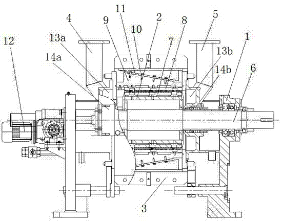
[0029] see figure 1 , The cylindrical single refiner of the present invention includes: a frame 1, a rotor 2, a casing 3, a pulp inlet pipe 4, a pulp outlet pipe 5 and a drive shaft 6 connected to a power source. In order to ensure the performance and quality of pulp, all parts in contact with pulp are made of stainless steel.

[0030] Among them, the frame 1 is used for the support and sealing of the rotor 2 and the discharge of the pulp after refining, and the rotor 2 is used for inputting pulp and transmitting the refining power, and a number of moving grinding plates 7 and fixed grinding plates 8 are installed on its outer peripheral surface To form a cylindrical refining zone. During the refining process, the gap between the fixed grinding plate 8 and the moving grinding plate 7 needs to be adjusted. Therefore, a certain grinding p...


PUM


Abstract

The invention discloses a cylindrical single-grinding grinder which comprises a frame, a rotor, a shell, a pulp inlet pipe, a pulp outlet pipe and a drive shaft. The drive shaft is connected with a power source. A plurality of movable grinding pieces and a fixed grinding piece are mounted on the outer circumference of the rotor to form a cylindrical grinding area. The fixed grinding piece is connected with a fixed grinding piece moving slider. A slope which can move axially is fixed inside the shell. A sliding plate for converting axial motion into radial motion is disposed between the slope and the fixed grinding piece moving slider. The cylindrical single-grinding grinder further comprises a fixed grinding piece advancing and retreating transmission mechanism. An output end of the fixed grinding piece advancing and retreating transmission mechanism is connected with the shell. The cylindrical single-grinding grinder has the advantages that the cylindrical single-grinding grinder is high grinding quality, stable in grinding state, and high in grinding efficiency compared with traditional dual-disc grinders and conical grinder, pulp performance is improved, and no-load consumption is lowered greatly under the same grinding capacity. In addition, the cylindrical single-grinding grinder is more convenient to operate and evident in economical benefits, the size and the length of the grinder are reduced greatly, and power of matching motors is lowered.

Description

technical field [0001] The invention relates to a refiner, in particular to a cylindrical single-refiner refiner, which is suitable for refining treatment of pulp raw pulp and waste paper pulp in the papermaking industry, and belongs to the field of pulp and papermaking. Background technique [0002] At present, the widely used refiners in the field of pulp and papermaking include double-disc refiners and conical refiners, but these two types of equipment have shortcomings: (1). In the pulping zone, the pulp flows in the direction of the centrifugal force, and the linear velocity of the refining zone changes from small to large from the center to the outer circle, which will lead to uneven refining quality; (2), in the conical refiner In the refining zone, due to the taper of the grinding disc, the direction of the pulp flow changes continuously with the component force of the centrifugal force. The closer the taper is to 90°, the closer the pulp flow direction is to the dir...

Claims


Application Information

Patent Timeline
Patent Type & Authority Patents(China)
IPC IPC(8): D21D1/38
Inventor 乐国培
Owner SUZHOU FEIYU PRECISION TECH
Why Eureka
Try Eureka