Sound-barrier simply-supported T-beam bridge

A sound barrier and simply supported technology, which is applied to bridges, bridge parts, bridge construction, etc., can solve the problems of not considering the load of the sound barrier, inconvenient installation of the sound barrier, and unsuitability of the sound barrier, so as to reduce the workload of maintenance and repair , Guarantee the effect of construction organization and arrangement, and reduce the impact

Active Publication Date: 2013-04-24
CHINA RAILWAY ENG CONSULTING GRP CO LTD
View PDF9 Cites 22 Cited by
  • Summary
  • Abstract
  • Description
  • Claims
  • Application Information

AI Technical Summary

Problems solved by technology

[0006] The purpose of this invention is to provide a kind of simply supported T-beam bridge with sound barrier, to overcome the load of the sound barrier in the design of simply supported T-beam of the prior art, and it is not convenient to install the sound barrier on the angle steel support, thereby not Suitability for setting up sound barriers

Method used


Image

  • Sound-barrier simply-supported T-beam bridge
  • Sound-barrier simply-supported T-beam bridge
  • Sound-barrier simply-supported T-beam bridge

Examples


Embodiment 1

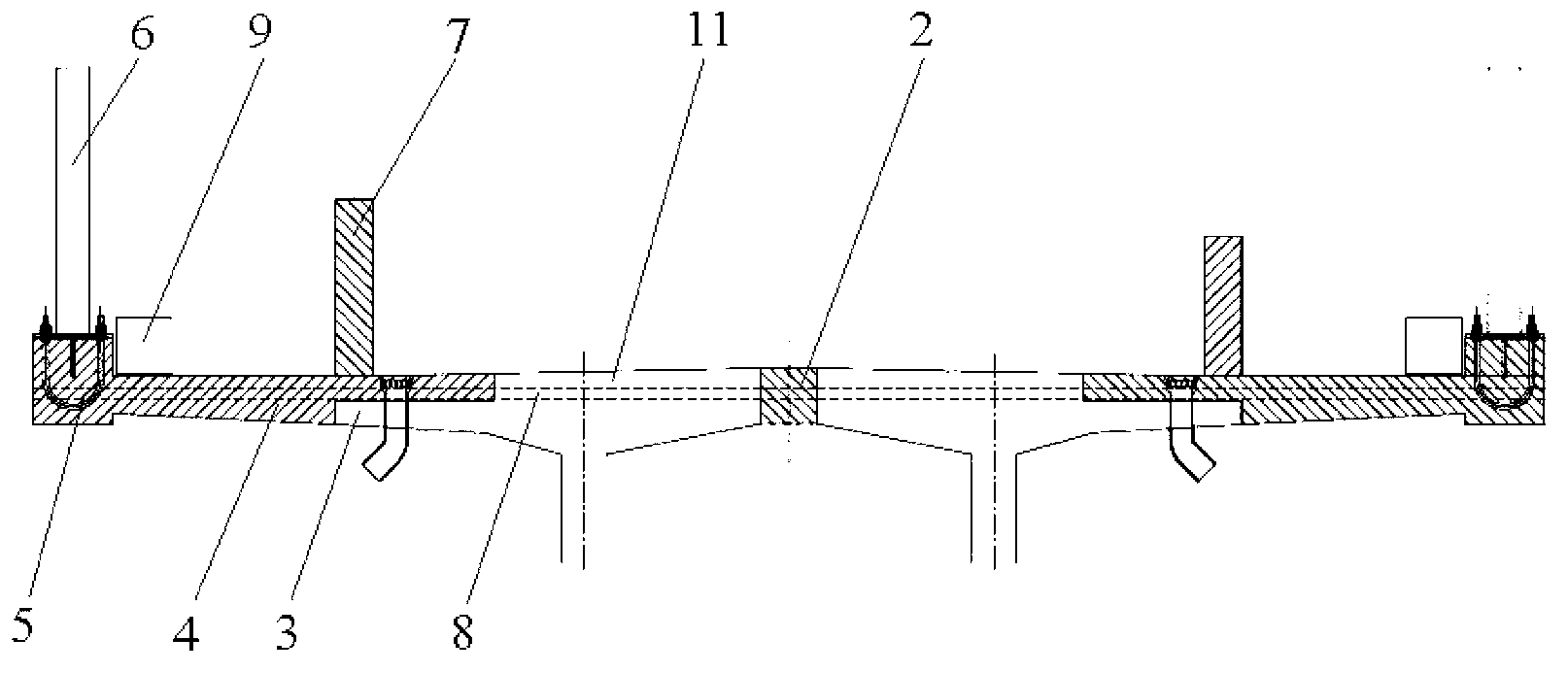
[0031] Such as figure 1 , 5 , 6, the simply supported T-beam bridge with sound barrier of the present embodiment is a single-track railway bridge, including two simply supported T-beams, and the simply supported T-beams are prefabricated beams.

[0032] Each simply supported T-beam is composed of multiple simply supported T-beam units connected end to end. The weight of a simply supported T-beam unit is less than 148 tons. The weight of a single piece of this simply supported T-beam unit meets the requirements of centralized prefabrication and railway transportation. It is beneficial to ensure the construction quality and construction organization arrangement, and the joints of each simply supported T beam unit are located on the pier 20; two simply supported T beams are horizontally connected together through the wet joint concrete of the diaphragm, and the two simply supported T beams A section of platform 3 protrudes from the outside of the beam, and the height of the plat...

Embodiment 2

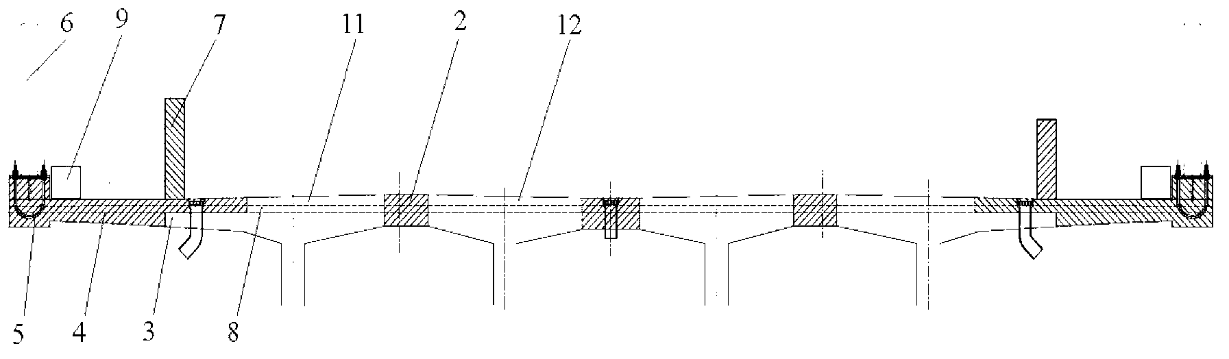
[0037] Such as figure 2 , 6 As shown, the simply supported T-beam bridge with sound barrier in this embodiment is a passenger-cargo double-track railway bridge, including four simply supported T-beams, and the simply supported T-beams are prefabricated beams.

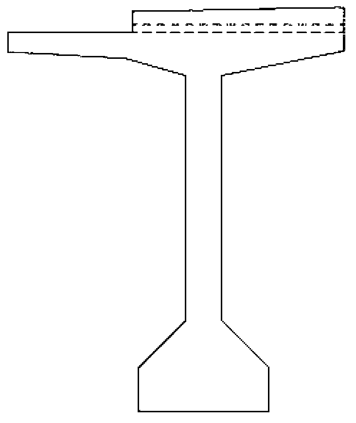
[0038] Each simply supported T-beam is composed of multiple simply supported T-beam units connected end to end. The weight of a simply supported T-beam unit is less than 148 tons. The weight of a single piece of this simply supported T-beam unit meets the requirements of centralized prefabrication and railway transportation. It is beneficial to ensure the construction quality and construction organization arrangement, and the joints of each simply supported T-beam unit are located on the pier 20; the four simply supported T-beams are horizontally connected together through the wet joint concrete of the diaphragm, and the simply supported T-beam units on both sides T beams are side beams (such as image 3 ), the simpl...


PUM


Abstract

The invention relates to the technical field of railway bridges and particularly discloses a sound-barrier simply-supported T-beam bridge which comprises a plurality of simply supported T-beams. Each simply supported T-beam is formed by connecting a plurality of simply supported T-beam units end to end. The simply supported T-beams are transversely connected through transverse partitions, wet joints and concrete. Concrete cast-in-place decks are arranged outside the simply supported T-beams on two sides. The upper surfaces of the simply supported T-beams, the upper surfaces of concrete connections and the upper surfaces of the concrete cast-in-place decks form an integral bridge deck. The whole integral bridge deck is provided with transverse prestressed bars. Sound-barrier column foundations are arranged outside the concrete cast-in-place decks, and sound-barrier columns are arranged at the sound-barrier column foundations. A sound barrier is arranged between each two adjacent columns. The performance of the railway bridge is improved, the railway bridge meets the requirement of providing the sound barrier by the aid of the integral bridge deck, sound barrier absorbs or isolates noise generated in running process of trains and the influence of the trains upon lives of nearby residents is reduced.

Description

technical field [0001] The invention relates to the technical field of railway bridges, in particular to a simply supported T-beam bridge with a sound barrier. Background technique [0002] A large part of railway bridges in my country adopts simply supported T-beam structure. A simply supported T-beam is composed of multiple simply supported T-beam units. Generally, single-track railway bridges are composed of two simply-supported T-beams. The railway bridge consists of four simply supported T-beams. The simply supported T-beam monolithic beam mentioned above is relatively small in size, does not require large-scale transportation and beam erection equipment, and can be transported over long distances through existing railway lines, so it is more flexible. [0003] The sound barrier is a facility set between the sound source and the receiver, so that the sound wave propagation has a significant additional attenuation, thereby reducing the impact of noise in a certain area w...

Claims


Application Information

Patent Timeline
Patent Type & Authority Applications(China)
IPC IPC(8): E01D2/00E01D19/12E01D19/00E01F8/00
Inventor 徐升桥刘玉亮李国强沈平徐立松梅山汪鹏翔简方梁
Owner CHINA RAILWAY ENG CONSULTING GRP CO LTD
Why Eureka
Try Eureka