Artistic window frame section bar, sliding window and casement window

A technology of artistic modeling and profiles, applied to windows/doors, leaf frames, building structures, etc., can solve the problems of increased production costs, high labor intensity, waste of materials and capital consumption, etc., to achieve saving and reduction in production process Production cost and the effect of improving manufacturing efficiency

Active Publication Date: 2015-06-17
罗继安
View PDF8 Cites 0 Cited by
  • Summary
  • Abstract
  • Description
  • Claims
  • Application Information

AI Technical Summary

Problems solved by technology

However, the existing combination windows are complex and cumbersome, because there are many types and models that are not universal, occupying a lot of warehouses, wasting materials, costing a lot of money, and labor-intensive manufacturing. Frame, sliding frame, side sealing frame, frame inner insert board, neutral frame, buckle, light enterprise, hook up, upper, inner lower, outer lower, sand fan frame, 90 degree corner, double sealing frame, jigsaw, outer The combination of inserting plate and solid slide requires a variety of structural materials, and the production of these structural materials requires many types of molds, which increases the production cost and increases the difficulty of production, low efficiency and high labor intensity.
In addition, the existing combined sliding windows and casement windows require different profiles to be used in combination, which has poor versatility and cannot be flexibly combined into sliding windows or casement windows according to needs. It is often necessary to manufacture profiles of various models and different structures on the windows. Increase the difficulty of manufacturing, also increase the number of molds for making profiles, and increase production costs

Method used


Image

  • Artistic window frame section bar, sliding window and casement window
  • Artistic window frame section bar, sliding window and casement window
  • Artistic window frame section bar, sliding window and casement window

Examples


Embodiment 1

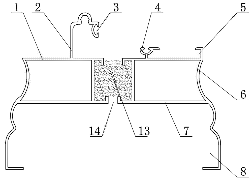
[0038] Embodiment one: see figure 1 , an art-shaped window frame profile, including a hollow cylindrical body formed by the combination of convex and concave arc surfaces. The hollow cylindrical body is composed of a top surface 1, a bottom surface 7 and two side surfaces 6. Parallel, the width of the bottom surface 7 is greater than the width of the top surface 1, one side of the outer surface of the top surface 1 is provided with a guide rail 2, and one side of the guide rail 2 is provided with a C-shaped card slot 3 for clamping the seal. The bottom of the side surface 6 is provided with a lower fixing groove 8, and the other side of the top surface of the hollow prismatic body is provided with a clamping groove 5, and a locking groove 5 is provided between the guide rail 2 on the outer surface of the top surface 1 and the clamping groove 5. track 4.

[0039] The side surfaces 6 of the hollow cylindrical body are formed by the combination of convex and concave arc surfaces...

Embodiment 2

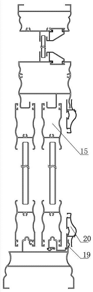
[0040] Embodiment two: see figure 2 , Embodiment 2 is basically the same as Embodiment 1. The symbols in the figure have the same representative meaning as Embodiment 1, and the similarities will not be repeated. The difference is that the window frame profile is a broken bridge profile, that is, the hollow column The left and right parts of the main body are connected by heat-insulating strips 9, which are clamped and fixed by the heat-insulating strip clamping structure, which is correspondingly arranged on the top surface of the hollow cylindrical body 1 and the bottom surface 7, the heat-insulating strip clamping structure includes a vertical support plate 12 perpendicular to the top surface 1 and the bottom surface 7, and one side of the vertical support plate 12 is distributed with fixed chucks 10 and dovetail chucks 11. The heat-insulating strips are rubber strips.

Embodiment 3

[0041] Embodiment three: see image 3 , Embodiment 3 is basically the same as Embodiment 1. The symbols in the figure have the same meaning as Embodiment 1. The same points will not be repeated. The difference is that the window frame profile is a broken bridge profile, that is, the hollow column The left and right parts of the body are connected by a glue injection connector 13, which is fixed by a glue injection structure arranged between the top surface 1 and the bottom surface 7 of the hollow body. The glue injection structure includes a glue injection cavity and a It consists of a glue injection port 14 arranged on the bottom surface.

[0042] During production, glue is injected into the glue injection cavity through the glue injection port 14, and after the glue is solidified, the top surface 1 is cut off to form a profile as shown in 3.


PUM


Abstract

The invention discloses an artistic window frame section bar, a sliding window and a casement window. The artistic window frame section bar comprises a hollow cylindrical body formed by butting and assembling a convex cambered surface and a concave cambered surface, the hollow cylindrical body is composed of a top surface, a bottom surface and two side surfaces, the bottom surface and the top surface are parallel with each other, width of the bottom surface is larger than that of the top surface, a guide rail is arranged on one side of the outer surface of the top surface, a C-shaped clamping groove is arranged on the side face of one side of the guide rail, lower fixing grooves are arranged at the bottoms of the two side surfaces, a clamping groove is arranged on the other side of the top surface, and a clamping rail is arranged between the guide rail on the outer surface of the top surface and the clamping groove. Movable guide rails are installed on the clamping groove and the clamping rail on the top surface of the section bar in matched mode to form the sliding window, and hinges are installed on the clamping rail of the top surface of the section bar in matched mod to form the casement window. The movable guide rails or hinges can be installed on the clamping groove and the clamping rail on the top surface of the section bar, the sliding window and the casement window can be combined, and the section bar has good generality and is wide in application range and easy to manufacture.

Description

technical field [0001] The invention relates to a window profile, a push-pull window and a casement window, in particular to an artistically shaped window frame profile, a push-pull window and a casement window. Background technique [0002] At present, combined sliding windows and casement windows are widely used in family housing and office housing. Sliding windows and casement windows are convenient to open and have good lighting and ventilation effects, and are deeply loved and welcomed by everyone. However, the existing combination windows are complex and cumbersome, because there are many types and models that are not universal, occupying a lot of warehouses, wasting materials, costing a lot of money, and labor-intensive manufacturing. Frame, sliding frame, side sealing frame, frame inner insert board, neutral frame, buckle, light enterprise, hook up, upper, inner lower, outer lower, sand fan frame, 90 degree corner, double sealing frame, jigsaw, outer It is composed ...

Claims


Application Information

Patent Timeline
Patent Type & Authority Patents(China)
IPC IPC(8): E06B3/06E06B3/263E06B3/26E06B3/36E06B3/46E06B3/96
Inventor 罗继安
Owner 罗继安
Why Eureka
Try Eureka