Ram air fan inlet housing

A technology for ram air fans and casings, used in air handling equipment, NACA-type air inlets, air inlets for turbine/propulsion units, etc., to solve the problem of insufficient air flow through heat exchangers, low ram air pressure And other issues

Active Publication Date: 2013-04-24
HAMILTON SUNDSTRAND CORP
View PDF6 Cites 8 Cited by
  • Summary
  • Abstract
  • Description
  • Claims
  • Application Information

AI Technical Summary

Problems solved by technology

[0003] While ram air works well under normal flight conditions, at lower flight speeds or when the aircraft is on the grou...

Method used


Image

  • Ram air fan inlet housing
  • Ram air fan inlet housing
  • Ram air fan inlet housing

Examples


Embodiment Construction

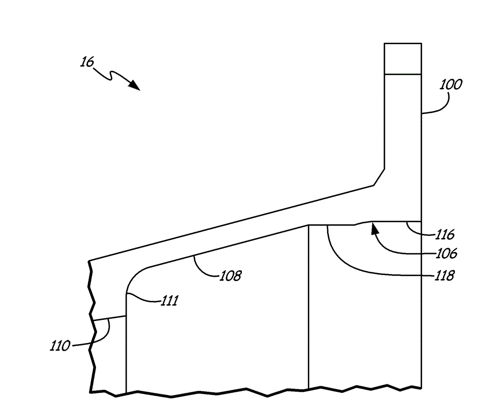
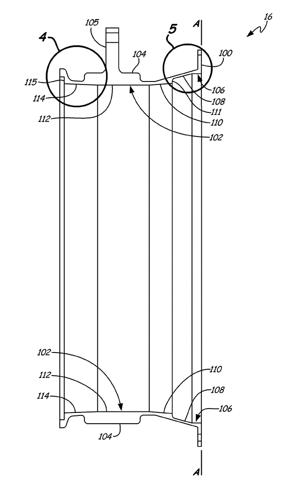
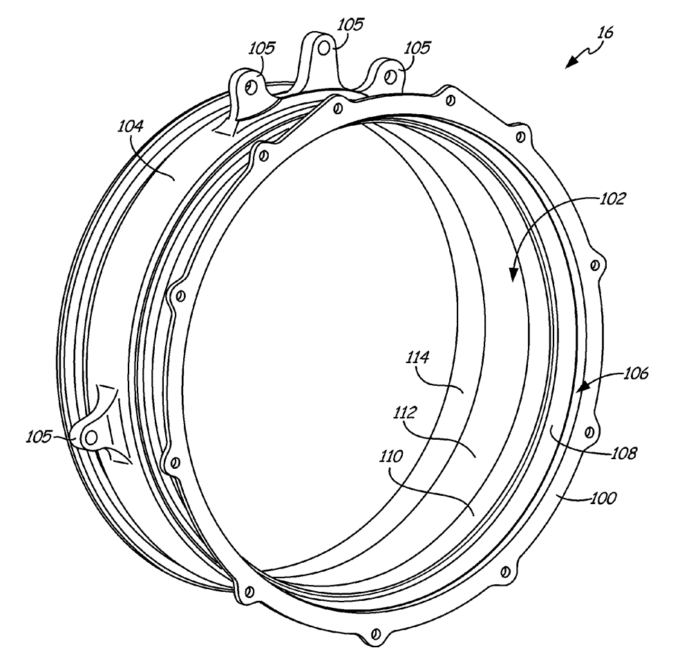
[0011] Conventional ram air fan assemblies in environmental control systems (ECS) employ a fan housing that includes a front or inlet section that surrounds the fan rotor. In this most basic form, such an inlet section has a cylindrical profile with a diameter greater than that of the fan rotor. The closer the fan rotor diameter is to the diameter of the inlet section, the higher the efficiency (air flow rate for a given fan speed) of the ram air fan. However, if the tolerances are too tight, the fan rotor may rub against the inlet section, resulting in damage to the inlet section and a reduction in fan efficiency. Once damaged by fan friction or normal wear, replacement of the inlet section requires replacement of the entire fan housing. This is a laborious and expensive process requiring removal of the ram air fan assembly from the ECS and almost complete disassembly of the entire ram air fan assembly. Finally, although uncommon, mechanical failure or rotor burst of a fan ...


PUM


Abstract

A ram air fan inlet housing for containing a ram air fan rotor. The inlet housing includes a flanged surface and an interior surface. The flanged surface is perpendicular to an axis of the inlet housing and defines a flange plane at an axial end of the inlet housing. The interior surface is symmetric about the axis of the inlet housing and includes a flange section, a transition section, an outlet section, a rotor section, and an inlet section.

Description

technical field [0001] The present invention relates to environmental control systems. In particular, the present invention relates to the inlet housing of the ram air fan assembly of the environmental control system of the aircraft. Background technique [0002] The Environmental Control System (ECS) on an aircraft provides conditioned air to the aircraft cabin. The conditioned air is at the temperature, pressure and humidity desired for the comfort and safety of the aircraft passengers. At or near the ground, the outside air temperature and / or humidity are often high enough that the air must be cooled as part of the conditioning process before being delivered to the aircraft cabin. At flight altitudes, the outside air is usually much cooler than desired, but is at such a low pressure that it must be compressed to an acceptable pressure as part of the conditioning process. Compressing outside air at flight altitudes heats the resulting pressurized air high enough that it...

Claims


Application Information

Patent Timeline
IPC IPC(8): F04D29/52F04D25/02
CPCY02T50/671Y02T50/44F04D25/02F02C7/32F04D29/52F04D29/701F04D29/522F04D29/644B64D2241/00B64D13/06F02C7/04B64D2013/0618B64D2013/0644F04D19/00Y02T50/40Y02T50/50Y02T50/60Y10T29/49323Y10T137/0536
Inventor S.E.罗森E.奇拉巴什V.S.理查森
Owner HAMILTON SUNDSTRAND CORP
Why Eureka
Try Eureka