
Automatic hub oiling machine

A technology of oil injection machine and wheel hub, which is applied in the direction of engine components, engine lubrication, mechanical equipment, etc. It can solve the problems of heavy workload, insufficient lubrication of the wheel hub, and high labor intensity, so as to improve efficiency and quality, and avoid fuel failure. In place, to avoid the effect of slow operation

Active Publication Date: 2013-04-24
GUANGDONG FUWA HEAVY IND
View PDF9 Cites 12 Cited by
  • Summary
  • Abstract
  • Description
  • Claims
  • Application Information

AI Technical Summary

Problems solved by technology

Due to the complex internal structure of the hub, it is impossible to accurately control the amount of refueling in each part during the manual refueling process, let alone refueling at two positions at the same time, and even dripping oil may occur
On the one hand, it causes waste of lubricating oil and pollutes the environment; on the other hand, the parts that need to be lubricated are not lubricated enough, which affects the normal use and maintenance of the hub
In addition, manual refueling requires a lot of manpower, a large workload, high labor intensity and has a certain impact on the health of workers

Method used


Image

  • Automatic hub oiling machine
  • Automatic hub oiling machine
  • Automatic hub oiling machine

Examples


Embodiment Construction

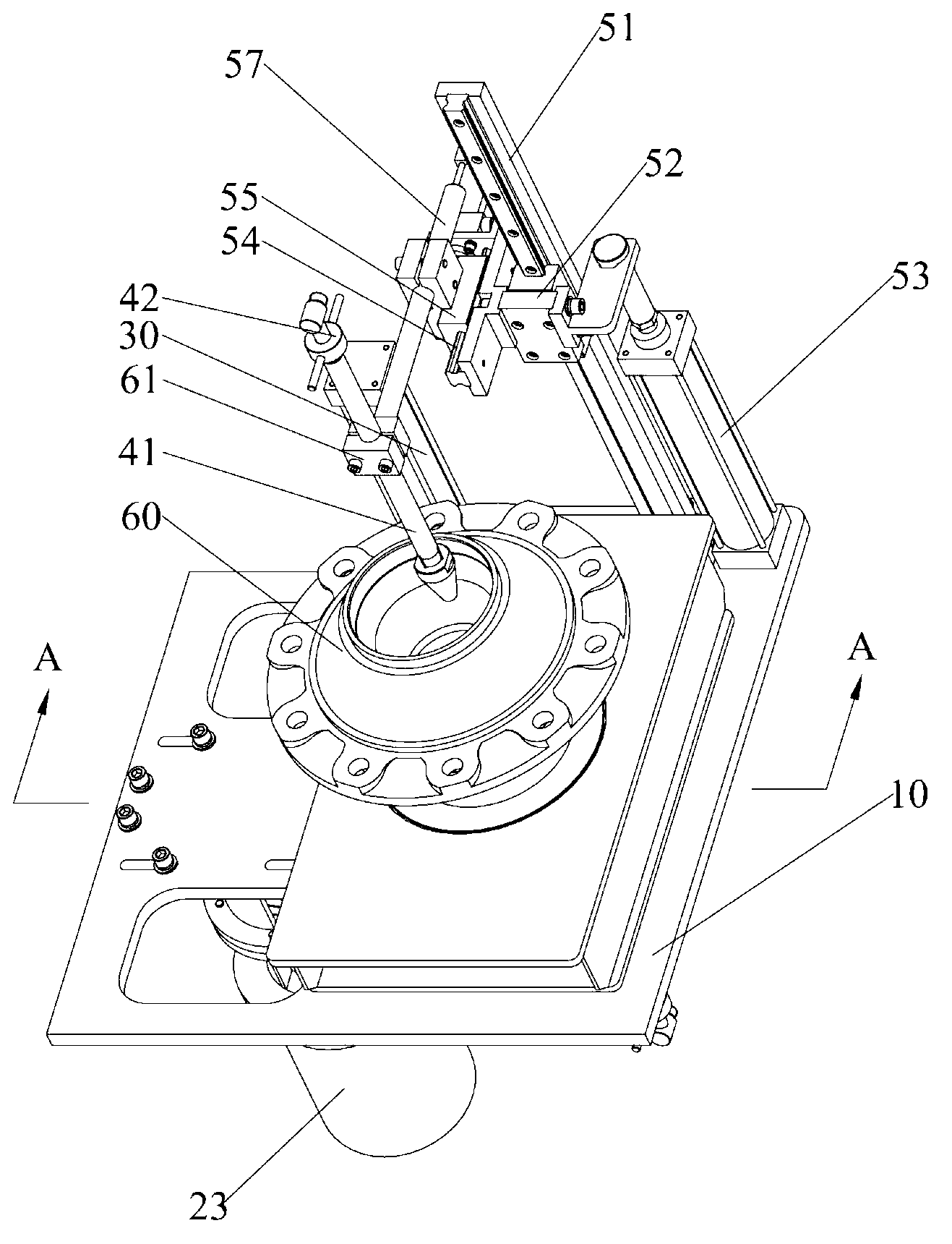
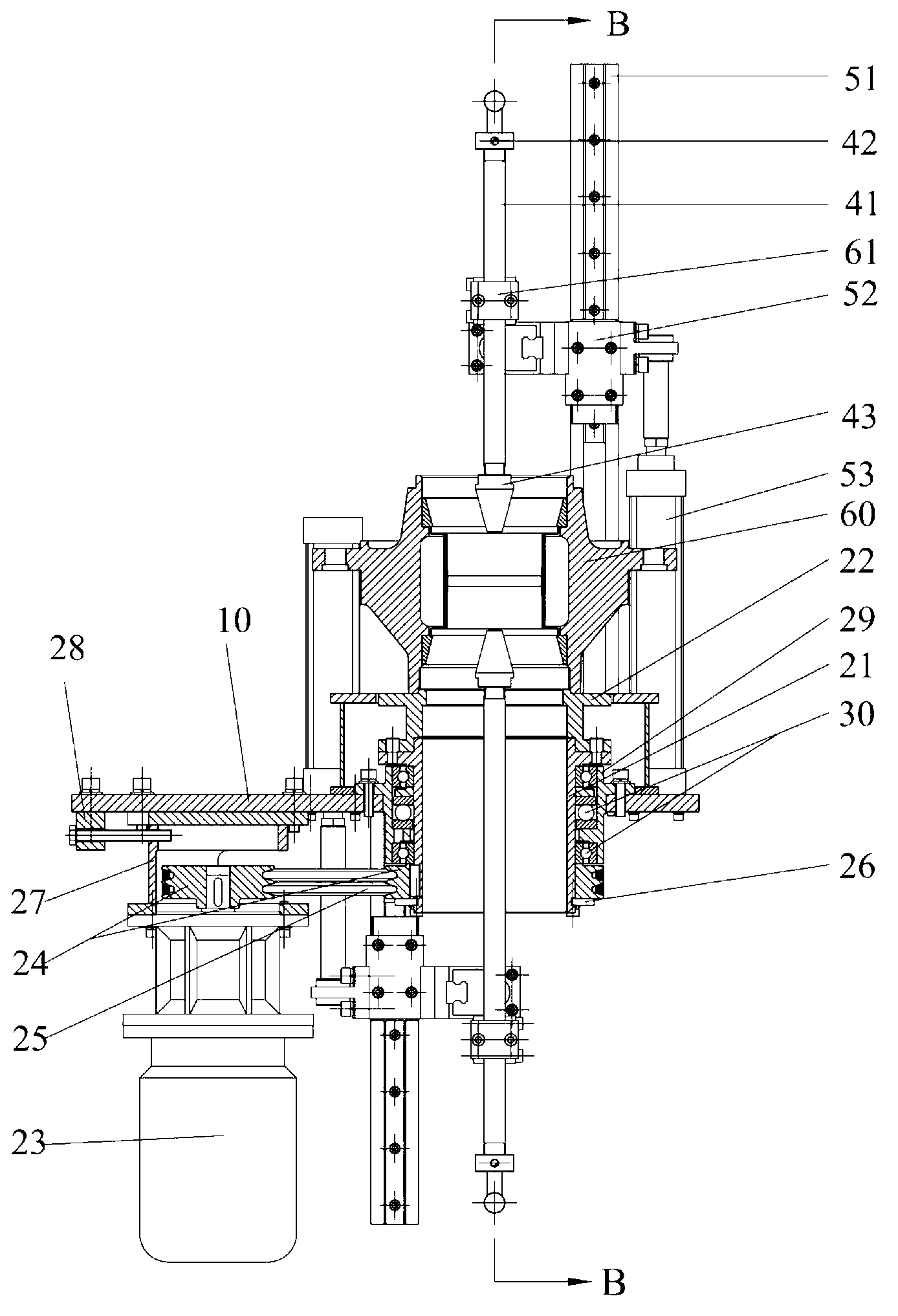
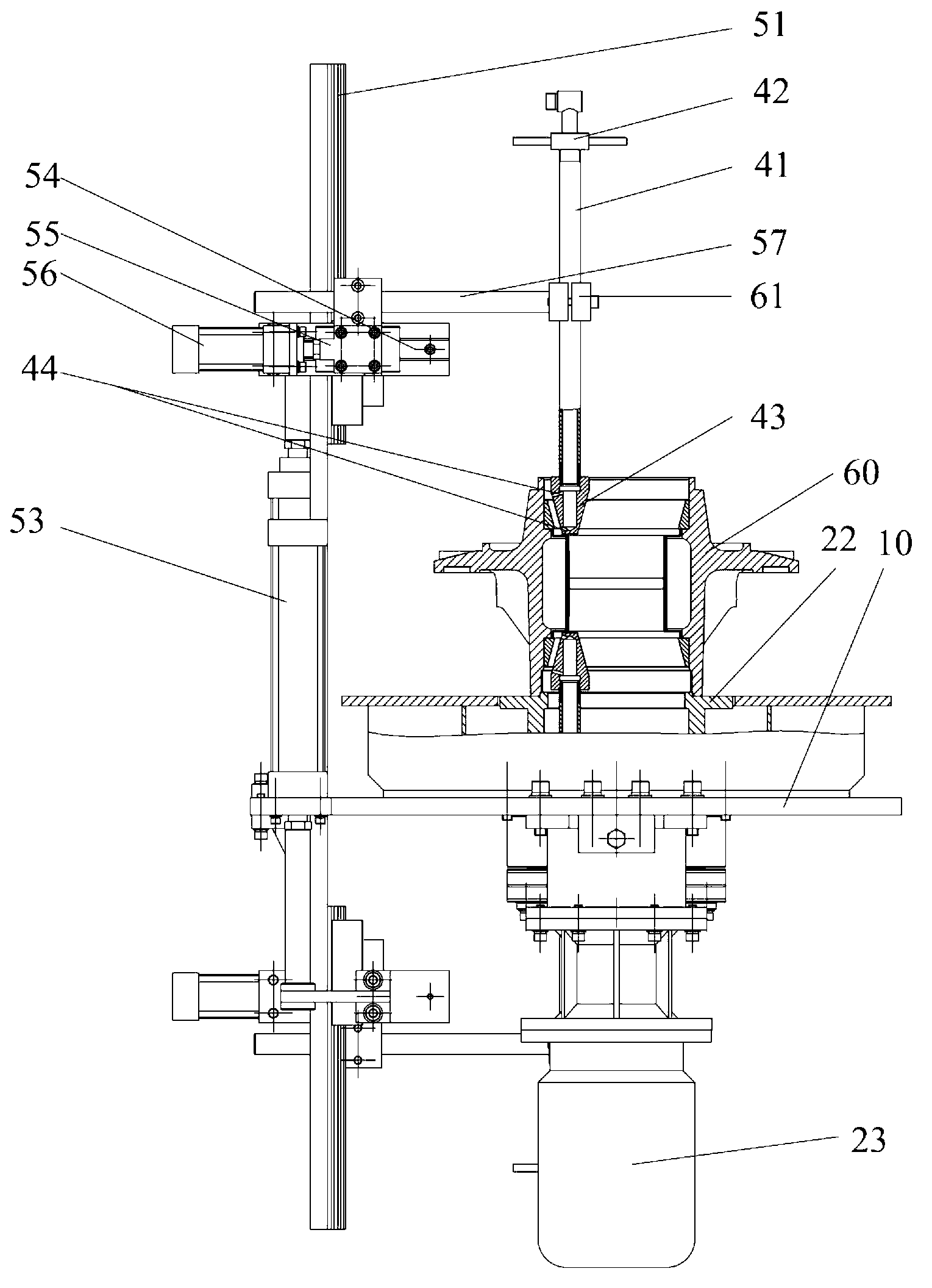
[0030] like Figure 1 to Figure 3 The shown wheel hub automatic oiling machine of the present invention includes a frame 10, a rotating mechanism installed on the frame 10, and an oiling device. The oiling device includes an oiling pipe 41 and a positioning device for driving the oiling pipe 41 into the wheel hub 60. The positioning device includes a first guide rail 51, a first slide seat 52 sliding up and down on the first guide rail 51, a second guide rail 54 arranged on the first slide seat 52, and a second guide rail 54 sliding left and right on the second guide rail 54. The sliding seat 55 and the connecting rod 57 whose two ends are respectively connected with the second sliding seat 55 and the oil injection pipe 41 . The upper end of the oil injection pipe 41 is provided with an oil pipe joint 42 , and the lower end is provided with an oil injection nozzle 43 , and the upper and lower parts of the side wall of the oil injection nozzle 43 are respectively provided with ...


PUM


Abstract

The invention relates to an automatic hub oiling machine. The automatic hub oiling machine comprises a frame, a rotating mechanism mounted on the frame and an oiling device, the oiling device comprises an oiling pipe and a positioning device for driving the oiling pipe to enter a hub, the positioning device comprises a first guide rail, a first slide seat, a second guide rail, a second slide seat and a connecting rod, the first slide seat slides vertically on the first guide rail, the second guide rail is arranged on the first slide seat, the second slide seat slides bilaterally on the second guide rail, and two ends of the connecting rod are connected with the second slide seat and the oiling pipe respectively. The automatic hub oiling machine is capable of uniformly filling lubricating grease on the hub and capable of oiling at two bearing positions in the hub simultaneously, manual operation slowness and oiling not in place are avoided, and production efficiency and production quality are improved.

Description

technical field [0001] The invention relates to an automatic oiling machine, in particular to an automatic oiling machine for wheel hubs. Background technique [0002] At the present stage in our country, the production of automobile wheels has entered the stage of large-scale production, and the operation of adding lubricating oil to the wheels is still mainly manual oiling. Due to the complex internal structure of the hub, it is impossible to accurately control the amount of refueling in each part during the manual refueling process, let alone refueling at two positions at the same time, and even oil dripping may occur. On the one hand, it causes waste of lubricating oil, and at the same time causes pollution to the environment; on the other hand, the parts of the hub that need to be lubricated are not lubricated enough, which affects the normal use and maintenance of the hub. In addition, manual refueling requires a lot of manpower, a large workload, high labor intensity...

Claims


Application Information

Patent Timeline
Patent Type & Authority Applications(China)
IPC IPC(8): F16N7/00
Inventor 吴志强黄土坤王景刚
Owner GUANGDONG FUWA HEAVY IND
Learn More