
Weighing pressure sensor with high oil injection efficiency and oil injection method

A pressure sensor, high-efficiency technology, applied in fluid pressure measurement by changing ohmic resistance, measuring fluid pressure, instruments, etc., can solve the problem of easy tearing and damage at right angles

Pending Publication Date: 2021-05-28
山东重心电子科技有限公司
View PDF6 Cites 1 Cited by
  • Summary
  • Abstract
  • Description
  • Claims
  • Application Information

AI Technical Summary

Problems solved by technology

[0004] In order to solve the problem that the right-angle part of the existing pressure sensor is easily torn and damaged due to stress accumulation, and how to improve the oil injection efficiency, the technical solution adopted in the present invention is: a weighing pressure sensor with high oil injection efficiency, including: a shell , the housing has a cavity, the cavity is filled with liquid, and one side of the housing is provided with an opening communicating with the cavity, the opening is provided with a bottom cover, and one side of the housing is There is a first through hole communicating with the cavity, a connector is arranged in the first through hole, and a diffused silicon sensor is arranged on the connector, and the casing is opposite to the bottom cover on the other side. The cavity wall has an outward first protrusion and an inward second protrusion, the highest point and the lowest point of the first protrusion form a first slope, and the highest point and the lowest point of the second protrusion A second slope is formed between the points, and the junction between the second slope and the side wall of the cavity has an inner chamfer;

Method used


Image

  • Weighing pressure sensor with high oil injection efficiency and oil injection method
  • Weighing pressure sensor with high oil injection efficiency and oil injection method

Examples


Embodiment 1

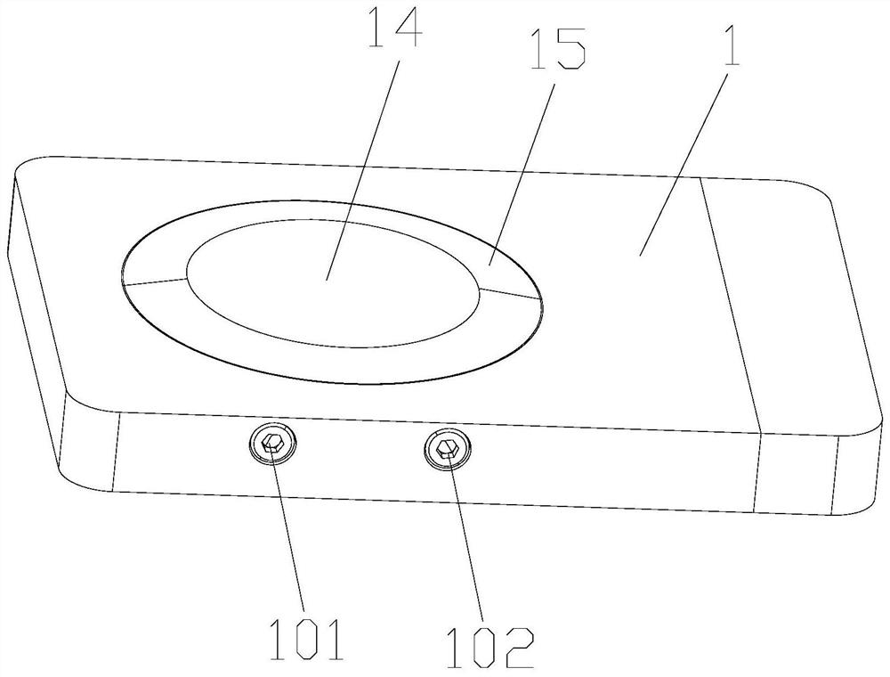
[0027] Such as figure 1 and figure 2 As shown, a weighing pressure sensor with high oil injection efficiency provided by the present invention includes: a housing 1, which has a cavity 11 inside, and the cavity 11 is filled with liquid, and the liquid can be Silicone oil, and one side of the housing 1 is provided with an opening communicating with the cavity 11, and the size of the opening matches the size of the cavity, and the opening is provided with a bottom cover 2 for sealing the cavity, so One side of the housing 1 is provided with a first through hole 12 communicating with the cavity 11, and a connector 13 is arranged in the first through hole 12, and the connector not only serves the purpose of sealing the first through hole, but also At the same time, the cavity end of the connector 13 is provided with a diffused silicon sensor, and the cavity wall on the side of the housing 1 opposite to the bottom cover 2 has an outward first protrusion 14 and an inward first pro...

Embodiment 2

[0036] Such as figure 1 and figure 2As shown, a weighing pressure sensor with high oil injection efficiency provided by the present invention includes: a housing 1, which has a cavity 11 inside, and the cavity 11 is filled with liquid, and the liquid can be Silicone oil, and one side of the housing 1 is provided with an opening communicating with the cavity 11, and the size of the opening matches the size of the cavity, and the opening is provided with a bottom cover 2 for sealing the cavity, so The edge of the bottom cover 2 is provided with a step structure 21, and correspondingly, the edge of the opening is also provided with a step structure on the housing that matches the step structure 21, and the bottom cover 2 is interference fit with the housing 1 One side of the housing 1 is provided with a first through hole 12 communicating with the cavity 11, and a connector 13 is arranged in the first through hole 12, and the connector not only serves to seal the first through ...

Embodiment 3

[0047] The present invention also provides an oil injection method, including the weighing pressure sensor with high oil injection efficiency described in any one of the above embodiments, and the oil injection method for oil injection to the weighing pressure sensor with high oil injection efficiency includes the following steps:

[0048] The vacuuming equipment is connected to the vacuum hole, and the oiling equipment is connected to the oiling hole;

[0049] Vacuuming equipment vacuumizes the cavity;

[0050] The oil injection device injects oil into the cavity.

[0051] The conventional cavity oiling method is to put a lot of pre-oiling equipment into a vacuum tank, which contains pre-filled oil, and then vacuumize the vacuum tank, and gradually fill the equipment cavity with oil as the vacuum degree increases. Though this kind method can carry out oiling to a lot of equipments at one time, efficiency is extremely low, and each oiling time varies from several hours to mor...


PUM

PropertyMeasurementUnit
Slopeaaaaaaaaaa

Abstract

The invention relates to a weighing pressure sensor with high oil injection efficiency and an oil injection method. The weighing pressure sensor comprises a shell, the shell is internally provided with a cavity, the cavity is filled with liquid, one side of the shell is provided with an opening, the opening is provided with a bottom cover, one side of the shell is provided with a first through hole, the first through hole is internally provided with a connector, the connector is provided with a diffused silicon sensor, the cavity wall of the other side, opposite to the bottom cover, of the shell is provided with an outward first protrusion and an inward second protrusion, a first inclined plane is formed between the highest point and the lowest point of the first protrusion, a second inclined plane is formed between the highest point and the lowest point of the second protrusion, and an inner chamfer is arranged at the joint of the second inclined surface and the side wall of the cavity. The pressure sensor is provided with the first inclined surface, the second inclined surface and the inner chamfer, so that the measuring range and the sensitivity are greatly improved. And moreover, the oil injection efficiency is high, oil injection is uniform, and no bubble is generated.

Description

technical field [0001] The invention relates to the field of pressure sensor equipment, in particular to a weighing pressure sensor with high oil injection efficiency and an oil injection method. Background technique [0002] As our road transportation network becomes more and more developed, correspondingly, the truck transportation business also develops rapidly. At the same time, with the refined management of transportation and the requirements of transportation safety, it is necessary to monitor the vehicle pressure and collect the micro-deformation data of the frame during transportation, and these need to be collected by pressure sensors. [0003] However, when the conventional pressure sensor is subjected to high pressure, the stress in the compressed part is relatively concentrated, mainly due to the stress accumulation at the right angle outside the pressure part and the right angle part or acute angle stress accumulation of the inner cavity wall, and tear damage o...

Claims


Application Information

Patent Timeline
IPC IPC(8): G01L9/06G01L19/14
CPCG01L9/06G01L19/14
Inventor 王星星
Owner 山东重心电子科技有限公司
Learn More