
A Method for Panorama Display and Defect Location of Pipeline Inner Wall

A positioning method, panorama technology, used in measurement devices, material analysis by optical means, instruments, etc.

Inactive Publication Date: 2015-09-23
XI'AN PETROLEUM UNIVERSITY
View PDF7 Cites 0 Cited by
  • Summary
  • Abstract
  • Description
  • Claims
  • Application Information

AI Technical Summary

Problems solved by technology

After consulting the relevant patents and literature, there is no such a method for the fusion of images acquired by the self-focusing lens array and the display of the inner wall image

Method used


Image

  • A Method for Panorama Display and Defect Location of Pipeline Inner Wall
  • A Method for Panorama Display and Defect Location of Pipeline Inner Wall
  • A Method for Panorama Display and Defect Location of Pipeline Inner Wall

Examples


Embodiment Construction

[0052] The present invention is described in detail below in conjunction with accompanying drawing.

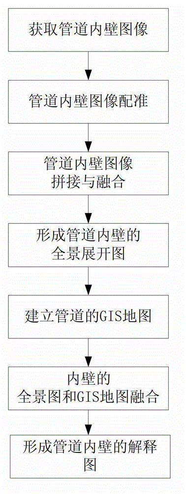
[0053] refer to figure 1 , a pipeline inner wall panorama display and defect location method, comprising the following steps:

[0054] Step 1: Translate and register the overlapping images of the inner wall obtained from the self-focusing lens array in various directions;

[0055] Image translation amount (x 0 ,y 0 ) is obtained as follows:

[0056] A. Read in two grayscale images I 1 and I 2 .

[0057] B. Image I respectively 1 and I 2 Do the Fourier transform, that is,

[0058] A=fft(I 1 ) B=fft(I2 )

[0059] C. Find the cross-power spectrum of the two images:

[0060] C=A.*conj(B) / norm(A.*conj(B))

[0061] Perform a two-dimensional Fourier inverse transform on the above formula, and find the peak value to get the translation amount (x 0 ,y 0 ).

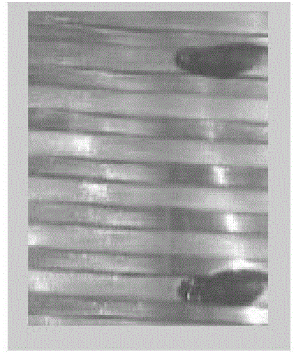
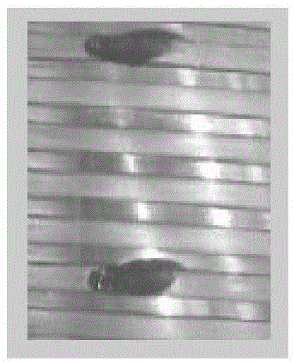
[0062] diagram 2-1 is to estimate the translation parameter by the phase correlation method, Figure 2-2 By ...


PUM


Abstract

A pipeline inner wall panorama display and defect location method includes: step 1, translating superimposed images of all orientations of a pipeline inner wall for alignment, wherein the superimposed images are obtained through a self-focusing lens array; step 2, zooming and rotating the superimposed images of all orientations of the pipeline inner wall obtained through the self-focusing lens array for alignment; step 3, splicing and fusing the superimposed images of all orientations of the pipeline inner wall obtained through the self-focusing lens array to form a panorama expansion drawing of the pipeline inner wall; step 4, building a geographic information system (GIS) map of the pipeline inner wall; and step 5, fusing the panorama expansion drawing, the GIS map and conformation explaining information of the pipeline inner wall to form a panorama expansion drawing which is relative to the pipeline length and positions in the inner wall where defects are located and intuitively displays various defects. Compared with the prior image processing and inter wall display method, the pipeline inner wall panorama display and defect location method is simple in arithmetic, intuitively displays inner wall images in map mode, and facilitates locating positions of the defects.

Description

technical field [0001] The invention relates to a method for image processing and information fusion obtained from a self-focusing lens array, in particular to a method for displaying a panorama of the inner wall of a pipeline and locating a defect. Background technique [0002] In many cases, it is often necessary to detect the contour shape, size, and inner wall defects of the inner wall of the pipeline, and sometimes it is necessary to conduct an overall evaluation of the continuity, integrity, and safety of the inner wall of some devices to determine whether it meets the functional requirements. . The device described in the patent No. 201010207380.8 mainly realizes the use of a self-focusing lens array as a crop lens, and the light cone as an image transmission device, and multiple objective lenses are placed sideways at the same time; multiple images are guided to an imaging sensor by the light cone; the light source Using the solution of ring self-focusing lens fiber...

Claims


Application Information

Patent Timeline
Patent Type & Authority Patents(China)
IPC IPC(8): G01N21/954G01B11/00G01B11/24
Inventor 贾惠芹王六鹏李周利张茹
Owner XI'AN PETROLEUM UNIVERSITY
Learn More