

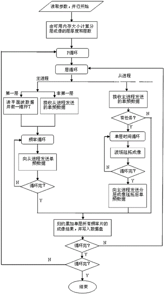
Layered continuation imaging method in wave equation prestack migration
An imaging method and pre-stack migration technology, which is applied in seismic signal processing and other directions, can solve the problems of low utilization of parallel nodes in memory requirements, large occupied content, inability to perform operations and migration calculations, etc.
- Summary
- Abstract
- Description
- Claims
- Application Information
AI Technical Summary
Problems solved by technology
Method used
Image

Examples
Embodiment 1
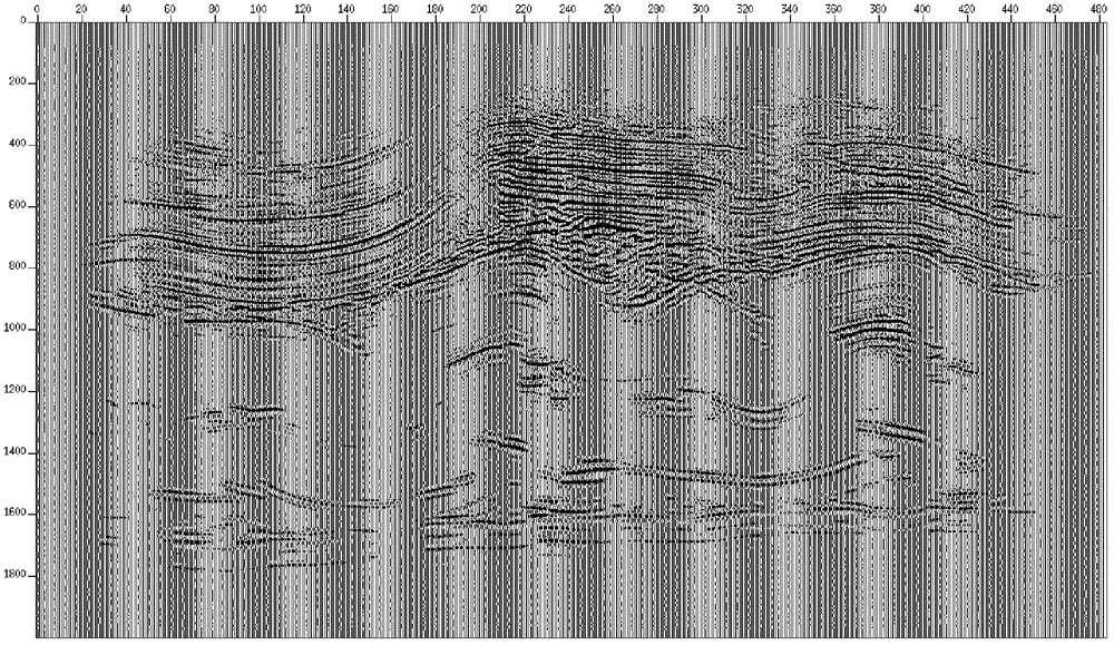
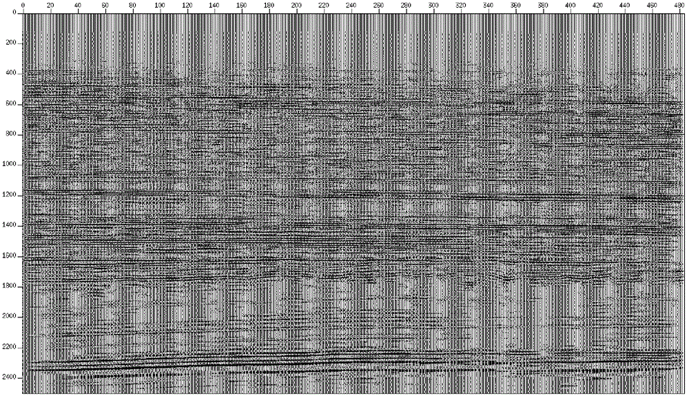
[0105] figure 2 and image 3 respectively represent embodiment 1 and embodiment 2
[0106] Among them, in Example 1, the full coverage area of a certain data in the south is 54.17km 2 , the bin size is 25m×25m, the sampling time is 6s, the sampling interval is 2ms, the number of sampling points is 3000, and the data volume of CMP gather is 70G. Using the non-hierarchical overall continuation imaging method, the memory requirement of the main process is 2457M, and the memory requirement of each slave process is 1006M. Using the layered continuation imaging method of the present invention, the maximum available memory space of the slave process is set to 350M, and the migration program divides the imaging depth into 3 layers, and each layer has a thickness of 1000 sampling points. The layered continuation imaging result is correct, figure 2 is the imaging section of a line obtained by using the present invention.
Embodiment 2
[0107] Example 2, a certain high-density data in the west, the bin size is 7.5m×7.5m, the sampling time is 7s, the sampling interval is 2ms, and the number of sampling points is 3500. To an area of 30km 2 Part of the seismic data is processed by wave equation prestack migration, the processing range is 360 (line) × 1450 (CDP), and the imaging depth is 3000 points. Using the non-hierarchical overall continuation imaging method, the memory requirement of the main process is 12.5G, and the memory requirement of each slave process is 5.83G. Due to the large memory requirement, a computing node with 8 cores and 16G memory can only use 2 cores for biasing. For shift computing, the utilization rate of parallel nodes is very low. Using the layered continuation imaging method of the present invention, in order to make all 8 cores of a node participate in the calculation, the maximum available memory space of the slave process is set to 1.6G, then the offset program divides the imaging...
PUM
 Abstract
Description
Claims
Application Information