Camera module test platform

A camera module and test platform technology, applied in photography, optics, instruments, etc., can solve problems such as unreliable test results of camera modules, and achieve smooth test process, high test efficiency, and good consistency

Active Publication Date: 2013-04-24
TRULY OPTO ELECTRONICS
View PDF3 Cites 34 Cited by
  • Summary
  • Abstract
  • Description
  • Claims
  • Application Information

AI Technical Summary

Problems solved by technology

[0006] In view of this, the purpose of the present invention is to provide a camera module test platform, to maintain the consistency of the camera module test environment, to solve the problem of unreliable test results of the camera module

Method used


Image

  • Camera module test platform
  • Camera module test platform
  • Camera module test platform

Examples


Embodiment 1

[0032] This embodiment discloses a camera module testing platform, comprising:

[0033] A base, the base is provided with a sliding shaft parallel to the surface of the base. The surface of the base is flat and preferably rectangular, and is used to carry the camera module and other components of the camera module test platform. The sliding axis is parallel to the surface of the base.

[0034] The first bracket is slidably arranged along the axial direction of the sliding shaft, that is, the first bracket can slide freely in the axial direction of the sliding shaft. The first bracket includes at least one first support column.

[0035] A close-range target, a stain test board, and a relay mirror are arranged on the first bracket.

[0036] A second bracket, the second bracket is arranged on the base, and a long-range target is set on the second bracket, and the distance between the long-range target and the surface of the base is greater than the distance between the relay m...

Embodiment 2

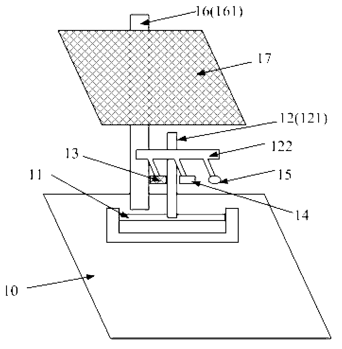
[0040] This embodiment discloses another camera module test platform, such as figure 1 shown, including:

[0041] The base 10 is provided with a sliding shaft 11 parallel to the surface of the base 10 . The surface of the base 10 is flat and preferably rectangular, and is used to carry the camera module and other components of the camera module test platform. The sliding shaft 11 is fixed on the surface of the base 10 through a shaft bracket 12 , and the axial direction of the sliding shaft 11 is parallel to the surface of the base 10 . Wherein, the length of the sliding shaft 11 depends on specific conditions, and is not limited here.

[0042] The first bracket 12 is slidably arranged along the axial direction of the sliding shaft 11 . The first bracket 12 includes a first support column 121, and a transverse support rod 122 parallel to the axial direction of the sliding shaft 11 is arranged on the first support column 121, and the transverse support rod 122 is connected t...

Embodiment 3

[0049] This embodiment discloses another camera module testing platform, which includes: a base, and a sliding shaft parallel to the surface of the base is arranged on the base. The sliding axis is parallel to the surface of the base.

[0050] The first bracket is slidably arranged along the axial direction of the sliding shaft, that is, the first bracket can slide freely in the axial direction of the sliding shaft. The first bracket includes at least one first support column.

[0051] A close-range target, a stain test board, and a relay mirror are arranged on the first bracket.

[0052]A second bracket, the second bracket is arranged on the base, and a long-range target is set on the second bracket, and the distance between the long-range target and the surface of the base is greater than the distance between the relay mirror and the surface of the base.

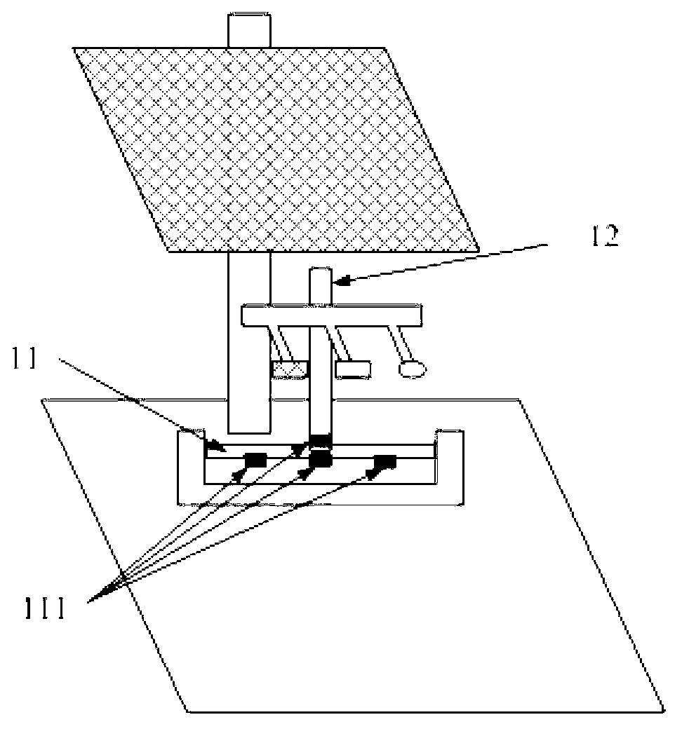
[0053] The difference from the above-mentioned embodiment is that, if figure 2 As shown, a positioning magnet 111 is...


PUM


Abstract

The invention discloses a camera module test platform which comprises a base, a first bracket, a close shot target, a stain test board, a relay lens and a second bracket, wherein the base is provided with a sliding shaft parallel to the surface of the base; the first bracket is arranged in a sliding manner along the axial direction of the sliding shaft; the close shot target, the stain test board and the relay lens are arranged on the first bracket; the second bracket is arranged on the base, and a long shot target is arranged on the second bracket; and the distance between the long shot target and the surface of the base is greater than the distance between the relay lens and the surface of the base. In a process of testing a camera module by use of the camera module test platform, the long shot focusing test, close shot focusing test and stain and vignetting test on the camera module can be finished simply by horizontally switching the close shot target, the stain test board and the relay lens. The camera module test environment has good consistency, and the reliability of the camera module test result is improved.

Description

technical field [0001] The invention belongs to the field of optical device testing, in particular to a camera module testing platform. Background technique [0002] After the camera module is assembled, it needs to be tested for its focus, stains, vignetting and other related performance. The existing test process generally includes: long-range focus, stain, vignetting test and close-range focus. [0003] Among them, the stain and vignetting test is generally done by manually covering the whiteboard. However, since the height of the hand cover is not exactly the same every time, the consistency of the camera module test environment is poor. [0004] Moreover, in the process of close-range focusing, the prior art needs to move the camera module under test to a close-range workstation. Therefore, the consistency of the camera module test environment will be relatively poor. [0005] Due to the poor consistency of the camera module test environment, the test results of the ...

Claims


Application Information

Patent Timeline
Patent Type & Authority Applications(China)
IPC IPC(8): G03B43/00
Inventor 李茂兴张粦钢李建华
Owner TRULY OPTO ELECTRONICS
Why Eureka
Try Eureka