Double-stator motor

一种双定子、定子的技术,应用在机电装置、电气元件、电动组件等方向,能够解决不能减少磁铁退磁、不能创建内部定子绕组空间良好关系、难以制造双定子电机等问题

Inactive Publication Date: 2013-04-24
DENSO CORP
View PDF8 Cites 11 Cited by
  • Summary
  • Abstract
  • Description
  • Claims
  • Application Information

AI Technical Summary

Problems solved by technology

Therefore it is difficult to make a double stator motor
[0007] (2) Due to the double structure, it is almost impossible to create a good relationship between the inner stator winding space and the cross-sectional area of ​​the core (core)
Therefore, the demagnetization of the magnet cannot be reduced
[0009] Because of these problems, using the system as disclosed in JP-A-H03-139156 did not lead to practical implementation of a double stator with ferrite magnets
Furthermore, even if the disclosed system is used as it is, the effect of reducing demagnetization cannot be expected

Method used


Image

  • Double-stator motor
  • Double-stator motor
  • Double-stator motor

Examples


no. 1 example

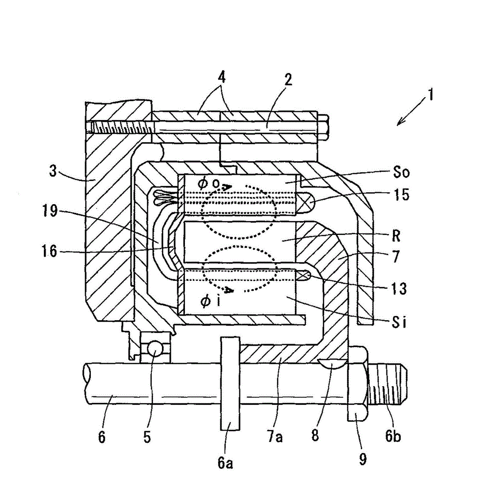
[0052] refer to Figure 1 to Figure 3 , Figure 4 (a) and Figure 4 (b), describes the first embodiment of the present invention. figure 1 is an overall schematic diagram showing the twin-stator motor 1 according to the first embodiment. as in figure 1 As shown in , the double-stator motor 1 includes a housing 3 , a motor case 4 , a shaft 6 , an annular rotor R, an inner stator Si and an outer stator So. The motor case 4 is fixed to the frame 3 via bolts 2 . The shaft 6 is rotatably supported by the motor case 4 via the bearing 5 . The rotor R is connected to the shaft 6 via a rotor wheel 7 . The inner stator Si is arranged radially inside the rotor R, and is fixed to the motor case 4 . The outer stator So is arranged radially outside of the rotor R, and is fixed to the motor case 4 . The rotor wheel 7 is made of, for example, non-magnetic SUS (Special Purpose Stainless Steel). The rotor wheel 7 comprises at its radial center a cylindrically shaped boss 7a. A stud 7a...

no. 2 example

[0075] now refer to Figure 11 , Figure 12 (a) and (b), the second embodiment of the present invention is described hereinafter. In the second embodiment and subsequent embodiments, the same or similar components as those in the first embodiment are assigned the same reference numerals in order to omit unnecessary explanation. Figure 11 is a partial cross-sectional view showing the rotor R and the inner and outer stators Si and So. Figure 12 (a) is a diagram showing the shapes of the inner and outer stator windings 13 and 15 viewed from the axial direction. Figure 12 (b) is a side view showing the shapes of the inner and outer stator windings 13 and 15 . Similar to the first embodiment, flat conductors are used as inner and outer stator windings 13 and 15 . The flat conductors each have a rectangular cross-section perpendicular to the longitudinal direction, and have the same cross-sectional area perpendicular to the longitudinal direction. In the first embodiment des...

no. 3 example

[0078] refer to Figure 13 , Figure 14 (a) and (b), the third embodiment of the present invention is described hereinafter. Figure 13 , Figure 14 (a) and (b) respectively correspond to the second embodiment Figure 11 , Figure 12 (a) and (b). In the third embodiment, as in Figure 13 As shown in , the conductors of the inner and outer stator windings 13 and 15 both have the same cross-sectional shape (substantially square) perpendicular to the longitudinal direction, and have the same cross-sectional area perpendicular to the longitudinal direction. exist Figure 13 A partial cross-sectional view of the rotor R, and the inner and outer stator windings Si and So is shown in , omitting the cross-sectional diagram showing the cross-section. as in Figure 14 As shown in (a) and (b), no twist is applied to the bridge 19 connected between the inner slot conductor 15 a 1 of the respective outer stator winding 15 and the slot conductor 13 a of the respective inner stator w...


PUM


Abstract

The invention discloses a double-stator motor. The motor has a magnet which has demagnetization trend and can be easily made compared with an existing motor. The double-stator motor of an example embodiment includes: an annular rotor connected to a rotary shaft and integrally rotates with the rotary shaft, an inner stator arranged radially inward of the rotor, and an outer stator arranged radially outward of the rotor. The rotor includes a plurality of segments annularly arranged in the circumferential direction, spaced apart from each other by a predetermined distance, and a plurality of permanent magnets each interposed between circumferentially adjacent segments, the permanent magnets being alternately magnetized in the circumferentially opposite direction. The rotor, the inner stator and the outer stator have the same number of poles. The inner and outer stator windings of the inner and outer stators, respectively, are connected so that their phases are reversed to each other. Thus, the magnetic fields generated by the magnetomotive forces of the inner and outer stators are applied to specific segments in parallel.

Description

technical field [0001] The present invention relates to electric machine constructions in which magnets with a tendency to demagnetize, such as ferrite magnets, can be used, and in particular to double-stator electric machines comprising annular rotors in which circumferentially magnetized permanent magnets are clamped separately in segmented The poles are arranged between the inner and outer three-phase stators respectively radially inner and outer of the rotor. Background technique [0002] In recent years, the mainstream motor is a synchronous motor in which neodymium magnets are embedded as permanent magnets. For such neodymium magnets, heavy rare earth metals such as dysprosium are indispensable as additive materials. However, as heavy rare earth metal prices skyrocket, when heavy rare earth metal magnets are applied to mass-produced motors, the future use of such heavy rare earth metal magnets risks being unsuitable for mass production. Therefore, in order not to use...

Claims


Application Information

Patent Timeline
Patent Type & Authority Applications(China)
IPC IPC(8): H02K16/04H02K1/14
CPCH02K3/28H02K21/14H02K1/2786H02K1/276H02K16/04H02K21/22H02K1/2791H02K3/50H02K23/36H02K3/505H02K3/52H02K3/522H02K3/521H02K23/38
Inventor 草濑新
Owner DENSO CORP
Why Eureka
Try Eureka