
Device for detaching suspension arm type component in narrow space

A cantilever, in-space technology, applied to hand-held tools, manufacturing tools, etc., can solve the problems of no supporting reaction force, narrow internal space, and the difficulty of ordinary disassembly tools to meet non-destructive disassembly.

Active Publication Date: 2013-05-01
FACTORY 5721 OF PLA
View PDF13 Cites 5 Cited by
  • Summary
  • Abstract
  • Description
  • Claims
  • Application Information

AI Technical Summary

Problems solved by technology

[0002] When the shaft and bearing are disassembled during the maintenance of machinery and equipment, the bearing is generally pulled out from the shaft end with a puller. This disassembly method is realized by the support reaction force provided by the cone surface of the positioning hole at the shaft end; for one end extending into the body The cantilever mechanical component of the cantilever mechanical component, its rotating shaft is assembled with the bearing on the body to form a tight fit connection relationship. When the cantilever mechanical component needs to be repaired and disassembled, if the outer surface of the body is used as the supporting surface of the disassembly tool, after applying external force It will damage the composite material on the outer surface of the fuselage, so it can only be disassembled inside the fuselage. However, due to the narrow internal space and the closure of the other port of the cantilever, there is no place to provide support and reaction force. It is difficult to meet the requirements of non-damage disassembly with ordinary disassembly tools. Require

Method used


Image

  • Device for detaching suspension arm type component in narrow space
  • Device for detaching suspension arm type component in narrow space
  • Device for detaching suspension arm type component in narrow space

Examples


Embodiment Construction

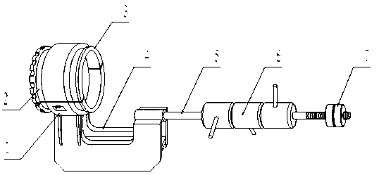
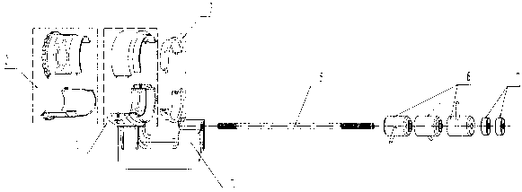
[0022] See Figure 1, figure 2 , the present invention includes a fixed sleeve 1, a bushing 2, an end face contact sleeve 3, a support 4, a pole 5, an inertia hammer assembly 6 and an impact screw sleeve 7, and the support 4 is a flat-bottomed U-shaped frame structure, and on its outside A fixed sleeve 1 is installed on the top, and the fixed sleeve 1 is set on the outside of the bushing 2. The inner side of the bushing 2 is fitted with the end face contact sleeve 3. One end of the support rod 5 is fixed on the inner top of the support 4. The inertia hammer assembly 6 is set on the rod 5, and the impact screw sleeve 7 is assembled on the other end of the strut 5.

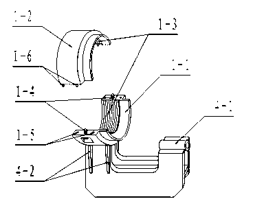
[0023] see image 3 , the present invention is provided with a set of reinforcing blocks 4-2 at the outer end of the support 4 and the mounting part of the fixing sleeve, and a pole fixing sleeve 4-1 is arranged at the inner top of the bearing, and the pole fixing sleeve 4-1 is connected with the pole 5 Screw conn...


PUM


Abstract

The invention discloses a device for detaching a suspension arm type component in a narrow space. The device comprises a fixing sleeve, a lining sleeve, an end surface contact sleeve, a supporting base, a supporting pole, an inertial hammer component and a striking screwed sleeve, wherein the supporting base is of a flat-bottom groove-shaped frame structure; the fixing sleeve is arranged at the top end of the outer side and is sleeved outside the lining sleeve; the inner side end of the lining sleeve and the end surface contact sleeve are assembled; the supporting pole is fixedly arranged at the inner side top of the supporting base; the inertial hammer component is sleeved on the supporting pole; and the striking screwed sleeve is arranged at the other end of the supporting pole. The device is simple in structure and convenient to operate, the working efficiency of detaching the suspension arm type mechanical component can be improved, and the damage to the suspension arm type mechanical component and a fixing component in a detaching process can be effectively avoided.

Description

technical field [0001] The invention relates to a dismantling device, in particular to a device for dismantling a cantilever component in a narrow space, and belongs to the technical field of objects used for connecting or dismounting by press fit. Background technique [0002] When the shaft and bearing are disassembled during the maintenance of machinery and equipment, the bearing is generally pulled out from the shaft end with a puller. This disassembly method is realized by the support reaction force provided by the cone surface of the positioning hole at the shaft end; for one end extending into the body The cantilever mechanical component of the cantilever mechanical component, its rotating shaft is assembled with the bearing on the body to form a tight fit connection relationship. When the cantilever mechanical component needs to be repaired and disassembled, if the outer surface of the body is used as the supporting surface of the disassembly tool, after applying exte...

Claims


Application Information

Patent Timeline
IPC IPC(8): B25B27/00
Inventor 胡树欣田海东李林王绍增王敬伟雷慧李华淑高永祥董玉金申文吉秦世生
Owner FACTORY 5721 OF PLA
Learn More