
Multi-visual-angle great-depth micro stereo visual-features fusion-measuring method

A feature fusion and stereo vision technology, applied in measurement devices, instruments, optical devices, etc., to overcome technical bottlenecks, overcome a large number of mismatches and mismatches, and solve the problems of occlusion and precise measurement of large-scale microscopic objects.

Inactive Publication Date: 2013-05-01
BEIJING UNIV OF TECH
View PDF5 Cites 21 Cited by
  • Summary
  • Abstract
  • Description
  • Claims
  • Application Information

AI Technical Summary

Problems solved by technology

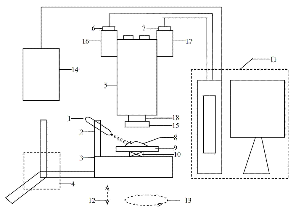
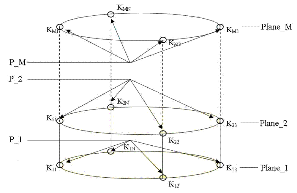
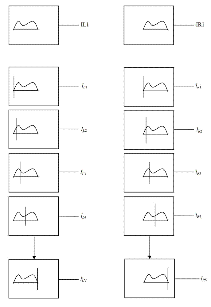
[0004] Aiming at the problems existing in the existing stereo microscope stereo vision measurement method, the present invention introduces a composite stereo microscope micro stereo vision measurement system that adds an auxiliary fringe projection system, a three-dimensional operating table, a rotary table and a lateral displacement table. The original stereo image pair is collected with a "barrel" node structure, and the original image sequence after the synthesis of the depth surface is output through the registration of the original image sequence at different node positions in the same depth surface, and the fusion of the original composite image sequence of different depth surfaces , output the original fused image after fusion, use this system to collect the fringe image, take the fringe edge pixel parallax as the main body, and the original image matching result in the local restricted area defined by the fringe edge as an auxiliary, and give the fringe composite disparity calculation result, its purpose It solves a large number of mismatching and mismatching phenomena caused by the existing stereoscopic vision measurement method of stereo microscope completely relying on the original image matching, improves the matching accuracy, and further solves the problems of occlusion and large depth measurement in this measurement method. Through fringe projection Realize the output of high-precision matching data

Method used


Image

  • Multi-visual-angle great-depth micro stereo visual-features fusion-measuring method
  • Multi-visual-angle great-depth micro stereo visual-features fusion-measuring method
  • Multi-visual-angle great-depth micro stereo visual-features fusion-measuring method

Examples


Embodiment Construction

[0080] The present invention is described in further detail now in conjunction with accompanying drawing. Figure 1-Figure 7 Show the flow chart of the fusion measurement method of multi-view large-depth micro-stereoscopic features involved in the present invention. As shown in the figure, the multi-view large-depth micro-stereoscopic feature fusion measurement method includes the following steps:

[0081] 1. "Barrel" node structure original image acquisition and fringe image acquisition

[0082] use figure 1 The compound stereo microscope microscopic stereo vision measurement system in the article collects the original stereo image pair in a "barrel-shaped" manner. The stereo microscope 5 adopts a general-purpose binocular structural optical microscope, and the resolution ratio of the left camera 6 and the right camera 7 is 1280 ×1024. The mobile controller 14 uses a pulse-type frequency-dividable controller with a maximum output frequency greater than 1 MHz. The three-dim...


PUM


Abstract

The invention relates to a multi-visual-angle great-depth micro stereo visual-features fusion-measuring method, which comprises the following steps of: acquiring an original stereo-image pair through a barrel-type node structure by using a compound stereomicroscope visual system, and providing accurate matching-parallax data through the image registration and the stripe registration at different node positions on the same depth surface, the fusion of original composite-image sequences on different depth surfaces and the local matching of original images, so that high-precision three-dimensional figures can be reconstructed. The method can be used for solving the problems of sheltering in micro stereo measurement and precise visual measurement of large-scale microscopic objects, and technical bottlenecks existing in an existing stereomicroscope visual-measuring method are essentially overcome.

Description

technical field [0001] The invention relates to a multi-view and large-depth microscopic stereoscopic feature fusion measurement method. The method uses a composite stereomicroscope microscopic stereoscopic measurement system to collect multi-dimensional space stereoscopic image pairs. The system includes an auxiliary fringe projection system, a three-dimensional console, Rotary stage, lateral displacement stage, stereo microscope and left and right cameras (using CCD cameras), especially involving the registration and fusion of projected fringe image sequences and multi-view and multi-depth plane stereo image sequences, using fringes as auxiliary boundary conditions Determine the local matching of the original image, output the fringe edge pixel parallax and local original image pixel parallax, and realize high-precision, unoccluded, and large-scale microscopic stereo measurement. Background technique [0002] Stereo microscope has two sets of optical paths, which form a ce...

Claims


Application Information

Patent Timeline
IPC IPC(8): G01B11/00G01B11/02G01B11/25
Inventor 王跃宗殷文佳张称称马国栋
Owner BEIJING UNIV OF TECH
Learn More