Breaking-braking operation mechanism for low-voltage circuit breaker
A low-voltage circuit breaker and operating mechanism technology, which is applied in the field of closing and opening operating mechanisms, can solve the problems of laborious operation and large resistance, and achieve the effect of simple manual operation
- Summary
- Abstract
- Description
- Claims
- Application Information
AI Technical Summary
Problems solved by technology
Method used
Image
Examples
Embodiment 1
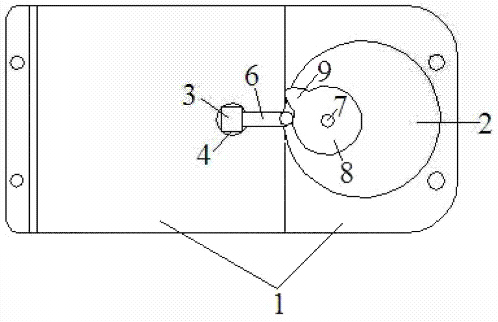
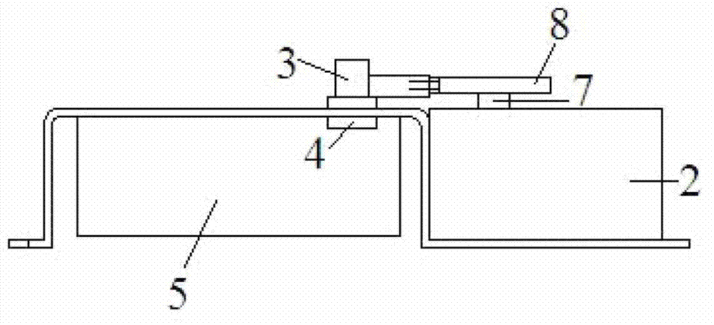
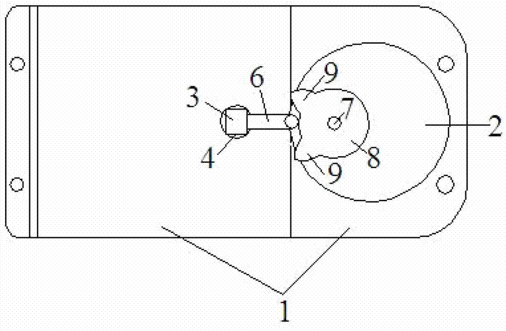
[0034] A closing and opening operating mechanism of a low-voltage circuit breaker, such as figure 1 and figure 2 As shown, it includes a frame 1, a motor 2, a drive shaft 3, a closing and opening transmission part 5, a switch handle, an intermittent transmission mechanism, and a controller. The motor 2 is carried by the frame 1 to provide electric driving force; the drive shaft 3 is mounted on the frame 1 through the drive shaft mount 4, and the drive shaft mount 4 is vertical and runs through the The rack 1 is set, and the driving shaft 3 is driven by the driving force; the closing and opening transmission part is driven by the driving shaft 3 to realize the closing and opening operation of the low-voltage circuit breaker; the switch handle (not shown in the figure logo) is connected with the drive shaft 3 to provide manual driving force; the intermittent transmission mechanism is arranged between the output shaft of the motor 2 and the drive shaft 3, and is composed of a d...
Embodiment 2
[0038] This example Figure 4 As shown, the difference from Embodiment 1 is that the actuating part is a flat disk 10 with a notch on one side socketed with the actuating transmission shaft 7, and the two ends of the notch in the circumferential direction are formed with pointed protrusions. The protruding portion 11 is in contact with the free end of the swing rod 6 and collides with the free end, thereby driving the swing rod 6 to swing within the limited range of motion. The working engineering of the second embodiment is obvious to those skilled in the art based on the working process of the first embodiment, and will not be repeated here.
Embodiment 3
[0040] The difference between this embodiment and Embodiment 1 is that the driven component is a gear, and the actuating component is a sector gear. When the motor 2 stops, the sector gear is disengaged from the driven gear. At this time, when the switch handle is manually operated to drive the drive shaft 3, since the gear does not contact the sector gear, no It will be subject to the resistance generated by the constant contact between the driven part and the actuating part in the prior art, so that the manual operation is relatively simple and labor-saving.
PUM
 Abstract
Description
Claims
Application Information
 - R&D
- Intellectual Property
- Life Sciences
- Materials
- Tech Scout
- Unparalleled Data Quality
- Higher Quality Content
- 60% Fewer Hallucinations
Browse by: Latest US Patents, China's latest patents, Technical Efficacy Thesaurus, Application Domain, Technology Topic, Popular Technical Reports.
© 2025 PatSnap. All rights reserved.Legal|Privacy policy|Modern Slavery Act Transparency Statement|Sitemap|About US| Contact US: help@patsnap.com


