
Eductor apparatus

a technology of eductor and apparatus, which is applied in the direction of mechanical apparatus, transportation and packaging, functional valve types, etc., can solve the problems of inability to efficiently control or extinguish fires by water alone, inability to carry, and complex systems, etc., to achieve safe collection, easy and safe cleaning, and avoid the effect of spillag

Active Publication Date: 2008-05-06
TASK FORCE TIPS
View PDF14 Cites 26 Cited by
  • Summary
  • Abstract
  • Description
  • Claims
  • Application Information

AI Technical Summary

Benefits of technology

The solution enables safe and controlled flushing of the eductor assembly, preventing chemical spills and allowing easy determination and manual alteration of the check valve position, making the system easier and safer to clean.

Problems solved by technology

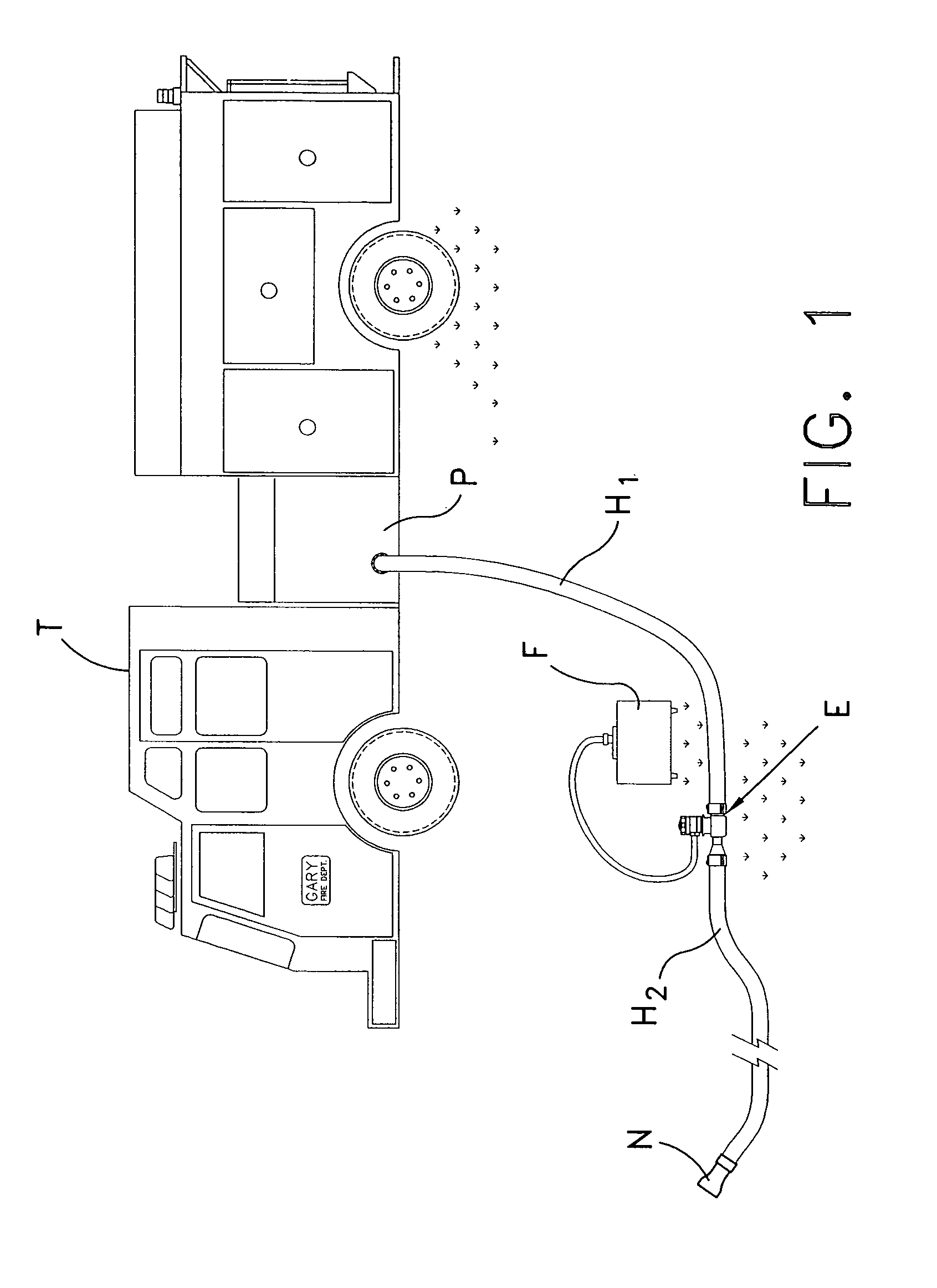
Fire fighting systems typically include a fire truck, such as truck T in FIG. 1, which includes a pumping unit P that pumps water under high pressure from a tanker truck or a nearby fire hydrant, through a fire hose H1, H2 and nozzle N. While water alone is sufficient for most fires, some fires cannot be efficiently controlled or extinguished by water alone.
Such systems are generally complicated and are not portable.
The chemical additives or foam concentrates are often corrosive and usually expensive.
While the check valve is important to prevent water backflow, it can be problematic with respect to cleaning the eductor valve E. In fire-fighting equipment back-flow typically occurs when the discharge nozzle N is shut off or when the hose H2 is kinked so that fluid discharge is terminated.
Without cleaning, the chemicals passing through the valve may congeal and foul the valve or the metering orifice used to control the quantity of chemical introduced into the water stream.
In an extreme case, the valve may be stuck open or closed.
This process is cumbersome, but perhaps more significantly this approach can be hazardous.
In particular, disengaging a eductor valve filled with a chemical additive of foam concentrate will necessarily result in a chemical spill.

Method used


Image

  • Eductor apparatus
  • Eductor apparatus
  • Eductor apparatus

Examples


Embodiment Construction

[0024]For the purposes of promoting an understanding of the principles of the invention, reference will now be made to the embodiments illustrated in the drawings and described in the following written specification. It is understood that no limitation to the scope of the invention is thereby intended. It is further understood that the present invention includes any alterations and modifications to the illustrated embodiments and includes further applications of the principles of the invention as would normally occur to one skilled in the art to which this invention pertains.

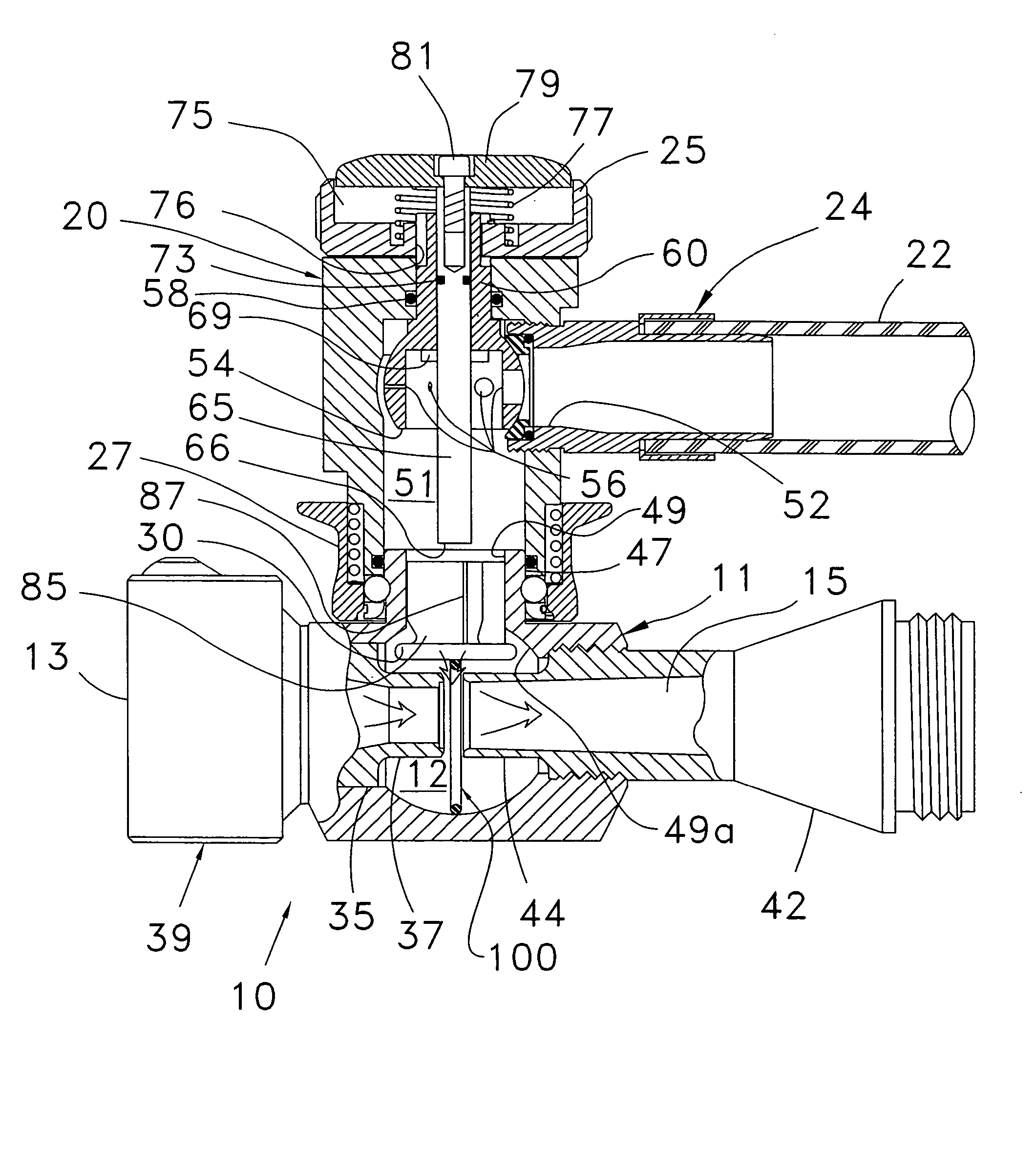
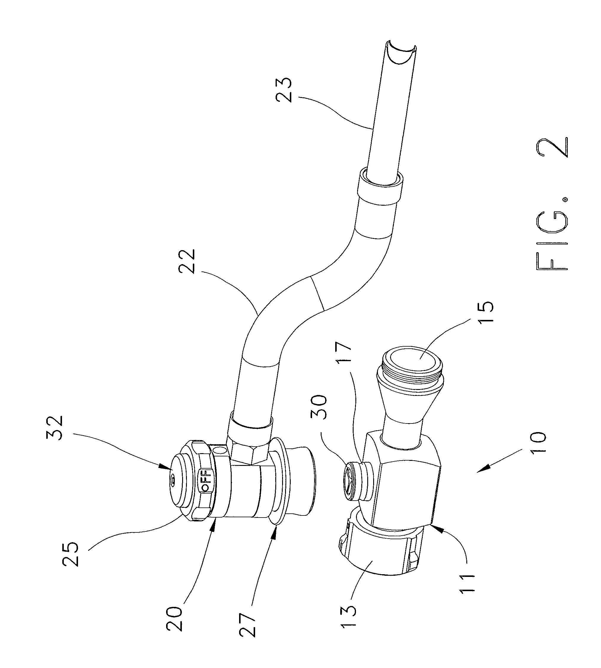
[0025]In accordance with one embodiment of the invention, the eductor valve E shown in FIG. 1 includes an eductor assembly 10, as illustrated in FIG. 2. This assembly includes a main body 11 having a water inlet 13 and an outlet 15. A foam inlet 17 intersects the inlet and outlet and is configured to mate with a metering head 20. The metering head 20 is connected to a suction hose 22 that terminates in a wand 23...


PUM

PropertyMeasurementUnit
pressureaaaaaaaaaa
pressureaaaaaaaaaa
suctionaaaaaaaaaa

Abstract

An eductor assembly includes an inlet connectable to a high pressure water source useful in firefighting, an outlet connectable to a fire hose and / or nozzle, and a venturi therebetween. An additive inlet communicates with the venturi so that a chemical additive, such as a foam concentrate, is educed into the output stream. A check valve is positioned at the additive inlet to open under venturi flow conditions and remain closed otherwise. An actuator is provided that holds the check valve in its open position while water flows through the eductor assembly under non-venturi conditions to produce a back flow through the additive inlet and ultimately through the additive fluid circuit, including the additive metering valve components. A return element may be disposed within the eductor body to return the check valve to its closed position when the back flow ceases.

Description

BACKGROUND OF THE INVENTION[0001]The present invention relates to fire-fighting equipment, and more specifically to equipment coupled to a fire hose or pipeline for integrating an additive to a water stream.[0002]Fire fighting systems typically include a fire truck, such as truck T in FIG. 1, which includes a pumping unit P that pumps water under high pressure from a tanker truck or a nearby fire hydrant, through a fire hose H1, H2 and nozzle N. While water alone is sufficient for most fires, some fires cannot be efficiently controlled or extinguished by water alone. In this case, certain chemical additives are introduced into the water line to be discharged onto the particular type of fire. Incidents involving flammable liquids or hazardous materials often require the use of a foam that is spread over the fire to starve the fire of oxygen or to suppress noxious vapors. For instance, Class A foam concentrates are used for wildland, rural and urban fire suppression on Class A fuels, ...

Claims


Application Information

Patent Timeline
Patent Type & Authority Patents(United States)
IPC IPC(8): G05D11/03
CPCA62C5/002A62C27/00B01F5/0413B01F5/0428B01F5/043B01F3/04446Y10T137/87643Y10T137/7938Y10T137/87627B01F23/235B01F25/31243B01F25/31242B01F25/312
Inventor STEINGASS, ROBERT W.
Owner TASK FORCE TIPS
Learn More