Motor operator, with inherent decoupling characteristics, for electrical power switches

a technology of motor operators and electrical power switches, which is applied in the direction of switches, contact mechanisms, switches, etc., can solve the problems of accessing manual elements, expensive and troublesome, and achieve the effect of inherent decoupling of invention

Active Publication Date: 2006-04-11
CLEAVELANDPRICE ENTERPRISES
View PDF9 Cites 26 Cited by
  • Summary
  • Abstract
  • Description
  • Claims
  • Application Information

AI Technical Summary

Benefits of technology

[0014]In part, the present invention resides in a motor operator with a motor shaft coupled to an operator output, attachable to a switch, by a drive assembly that has elements with mutual engagement (coupling) temporarily during a period of force application to the output sufficient for switch operation followed, without any required manual or power intervention, by disengaging (decoupling). In this respect, the apparatus of the invention exhibits decoupling as an inherent part of its operation. It does not require a positive act to be performed, following a switch operation, to decouple manually or under power, including what some might regard as “automatic” decoupling in which a control system senses an operation and, without human intervention, drives the operator back to a decoupled state. The inherent decoupling of the invention is achieved without requiring a sensing signal to tell the operator when it may become decoupled.
[0015]Manual operation is easy to perform with the decoupled operator. The motor driven temporarily mutually engaging elements of the drive assembly do not need to meet during a manual operation.
[0017]The inherent decoupling of the motor drive can facilitate performance of a manual operation, even with a pole-top motor operator and switch installation. A worker does not need to perform a positive act to achieve decoupling and does not need to rely on operation of a control system (that might be inoperable due to loss of power) to achieve the decoupled state. A worker can tell decoupling has occurred by, for example, status indicators at ground level or by looking at the position of an operating member (e.g., a laterally extending bar or plate), that is continuously fixed to the operator output shaft, to see if the switch is open or closed. In normal use, there is no need for a worker to be immediately at the operator. Manual operation of an overhead switch from the ground is readily performed.
[0020]The lack of complexity of the required structure enhances its reliability and convenience in use. In some forms, after the switch travels to the open or closed position (whether or not the switch itself has spring-loaded contacts), the operating member of the motor operator hits its end-of-travel stops (e.g., posts fixed to the housing or support structure) and the force (torque) transfer is greater than the maximum force that can be held by the temporarily engaged parts of the drive elements; their relative motion continues to reach the inherently decoupled state. Further, a simple limit switch at each of the open and closed positions on one of the drive elements can be triggered by the other drive element to turn off power to the motor.

Problems solved by technology

While such operators may be similar to the former ground-based units in some respects, e.g., including remotely initiated power operation, if the same features for manual operation are retained there is the problem of accessing the manual elements, such as requiring a worker to climb up to the operator, or use of a lift-truck, which is expensive and troublesome.

Method used


Image

  • Motor operator, with inherent decoupling characteristics, for electrical power switches
  • Motor operator, with inherent decoupling characteristics, for electrical power switches
  • Motor operator, with inherent decoupling characteristics, for electrical power switches

Examples


Embodiment Construction

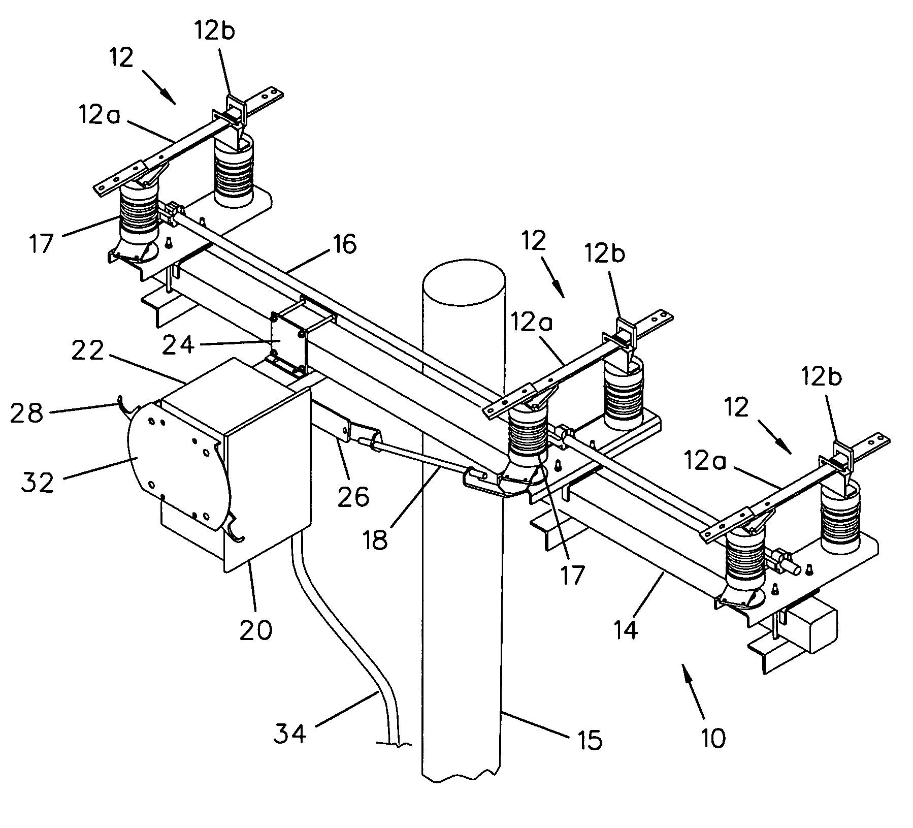
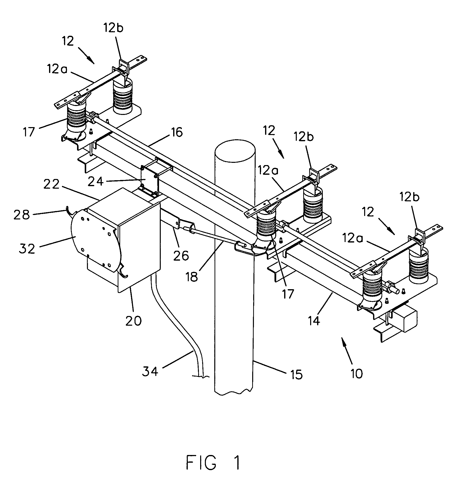
[0028]FIG. 1 shows a typical pole-top installation of an electrical power switch 10 and a motor operator 20 in accordance with the invention. The illustrated switch 10 is a three-phase distribution switch with three switch poles 12 arranged for ganged operation on a cross-arm 14 on a utility pole 15. Each of the switch poles 12 includes a first switch contact 12a that is movable to a closed or open switch position in relation to a second switch contact 12b that is fixed. The three movable contacts 12a are each mechanically coupled to a switch operating rod 16 for operation together. The rod 16 is subject to linear movement effecting switch operation by rotation of one switch-pole movable insulator post 17 that has a mechanical linkage 18 to an output member of the motor operator 20. The illustrated switch 10 is sometimes referred to as a movable insulator type of switch because of the force transmitted through rotating insulators that support the movable contacts 12a. In the orienta...


PUM


Abstract

A motor of a power switch motor operator has its motor shaft coupled to the output member of the operator, that connects with the power switch, through a drive assembly with at least one drive element continuously linked to the motor shaft, but not to the output member, and at least another drive element continuously linked to the output member, but not to the motor shaft. Temporary engagement of the mentioned drive elements, with motor operation of the power switch, is effected by temporary force transfer parts on the drive elements (e.g., a fixed post on one engaging a spring-loaded cam bar on the other) which inherently disengage following force transfer sufficient to operate the switch. The inherently decoupled state allows immediate straightforward manual operation by an operating member, even when the motor operator is at an overhead switch location, without any turning of the motor or engaging of the temporary force transfer parts during the manual operation.

Description

BACKGROUND OF THE INVENTION[0001]1. Field of the Invention[0002]The invention relates generally to electrical power switchgear with motor operators and, more particularly, to motor operators for power switches with a drive system that facilitates switch operation by force other than from the motor of the operator, such as manually applied force, even for switches at overhead (or pole-top) locations.[0003]2. Background Art[0004]Motor operators are widely used in combination with power switches. A variety of operators are in use with various features to permit a switch operation to be performed manually. These have included operators with features for mechanically decoupling the operator's drive system from the motor. Decoupling has taken a number of different forms.[0005]Power switches are applied at a variety of locations including some at surface, or ground level, locations relatively easily accessed for manual decoupling and switch operation and some at overhead (or pole-top) loca...

Claims


Application Information

Patent Timeline
Patent Type & Authority Patents(United States)
IPC IPC(8): H01H3/20
CPCH01H3/227H01H3/58H01H3/26H01H3/54
Inventor ANDREYO, JOSEPH K.
Owner CLEAVELANDPRICE ENTERPRISES
Why Eureka
Try Eureka