
Dead time effect compensation method and device

A dead-time compensation and dead-time effect technology, applied in output power conversion devices, electrical components, control systems, etc., can solve problems such as harmful dead-time effects, reducing motor system efficiency, and reducing the effective value of motor controller output voltage. , to achieve the effect of improving control efficiency

Active Publication Date: 2013-05-01
深蓝汽车科技有限公司
View PDF5 Cites 16 Cited by
  • Summary
  • Abstract
  • Description
  • Claims
  • Application Information

AI Technical Summary

Problems solved by technology

However, the existence of the dead time brings a very harmful dead time effect to the three-phase inverter, that is, the existence of the dead time makes the duty cycle of the actually output three-phase SVPWM waveform lower than the given duty cycle, wherein, The duty cycle is the proportion of the high level in one cycle; when the duty cycle is lower than the given duty cycle, the effective value of the output voltage of the motor controller will be reduced, which in turn will cause the Control inefficiencies, ultimately reducing motor system efficiency

Method used


Image

  • Dead time effect compensation method and device
  • Dead time effect compensation method and device
  • Dead time effect compensation method and device

Examples


Embodiment Construction

[0048] The following will clearly and completely describe the technical solutions in the embodiments of the present invention with reference to the accompanying drawings in the embodiments of the present invention. Obviously, the described embodiments are only some of the embodiments of the present invention, not all of them. Based on the embodiments of the present invention, all other embodiments obtained by persons of ordinary skill in the art without making creative efforts belong to the protection scope of the present invention.

[0049] In order to solve the problem that the current three-phase duty cycle of the output waveform of the three-phase inverter circuit of the motor controller is lower than the given three-phase duty cycle due to the existence of the dead time, which affects the control efficiency of the motor controller, the embodiment of the present invention provides A dead-zone effect compensation method and device are provided to realize the compensation for...


PUM


Abstract

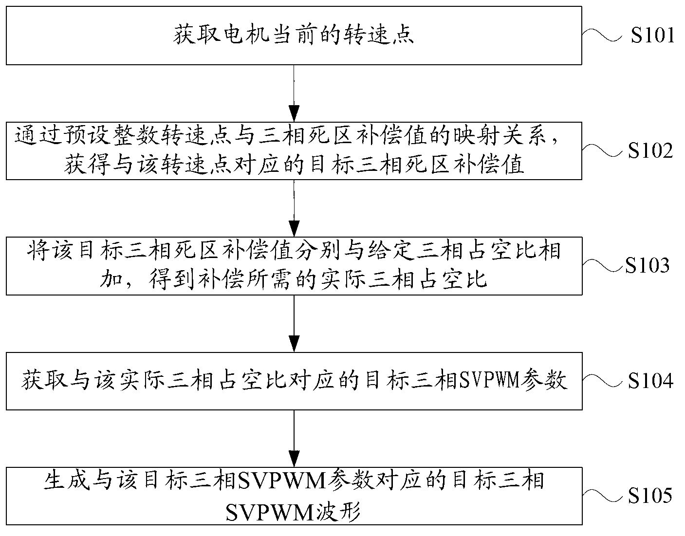
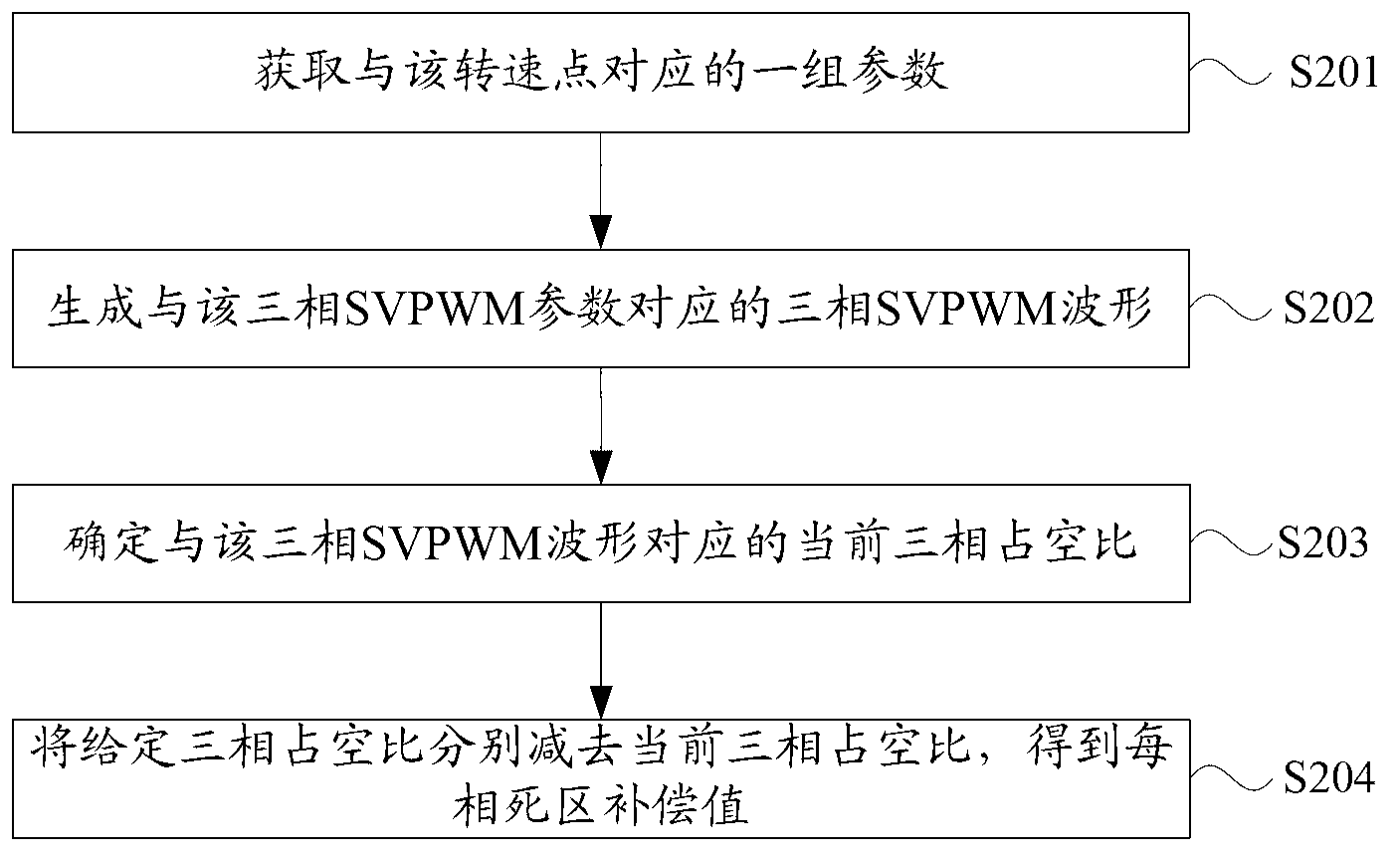
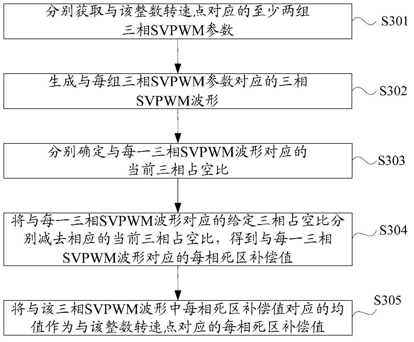
The invention discloses a dead time effect compensation method and a dead-time effect compensation device. The method comprises the following steps of: presetting a mapping relation between an integer rotating speed point and a three-phase dead time compensation value to obtain a target three-phase dead time compensation value which corresponds to a current rotating speed point; adding the target three-phase dead time compensation value with a given three-phase duty ratio to obtain a practical three-phase duty ratio needed by compensation; and further obtaining a target three-phase SVPWM (Space Vector Pulse Width Modulation) parameter which corresponds to the practical three-phase duty ratio to generate a target three-phase SVPWM waveform so as to finish compensation for the three-phase SVPWM waveform under the rotating speed point. According to the method and the device, the problem that the current three-phase duty ratio of the three-phase inverter circuit output waveform of a motor controller is lower than the given three-phase duty ratio due to the presence of the dead time is solved, and the control efficiency of the motor controller is further increased.

Description

technical field [0001] The invention belongs to the technical field of motor control, and in particular relates to a dead zone effect compensation method and device suitable for motor controllers and based on space vector pulse width modulation (SVPWM). Background technique [0002] At present, permanent magnet synchronous motor controllers usually use Space Vector Pulse Width Modulation (SVPWM, Space Vector Pulse Width Modulation) to control the motor. Among them, SVPWM is a relatively novel control method that has developed rapidly in recent years. It uses the pulse width modulation wave generated by the specific switching mode composed of six power switching elements of the three-phase power inverter to make the output three-phase waveform as close as possible to an ideal sine wave. [0003] In the existing three-phase inverter circuit of the motor controller, ideally, the upper and lower power switching devices of the same bridge arm of the three-phase inverter circuit ...

Claims


Application Information

Patent Timeline
IPC IPC(8): H02P27/06H02M7/00
Inventor 王璐陈健范旭红金国庆任勇
Owner 深蓝汽车科技有限公司
Learn More