
Method for recontouring a compressor or turbine blade or vane for a gas turbine

A technology for turbine blades and gas turbines, applied in turbines, blade support elements, machines/engines, etc., can solve problems such as troublesome on-site execution, inability, and troublesome repair methods, and achieve the effect of reducing material loss

Inactive Publication Date: 2013-05-01
LUFTHANSA TECH AG
View PDF8 Cites 2 Cited by
  • Summary
  • Abstract
  • Description
  • Claims
  • Application Information

AI Technical Summary

Problems solved by technology

However, this repair method, including the dismantling of the gas turbine, is also extremely cumbersome and cannot or can only be carried out on-site with great difficulty.

Method used


Image

  • Method for recontouring a compressor or turbine blade or vane for a gas turbine
  • Method for recontouring a compressor or turbine blade or vane for a gas turbine
  • Method for recontouring a compressor or turbine blade or vane for a gas turbine

Examples


Embodiment Construction

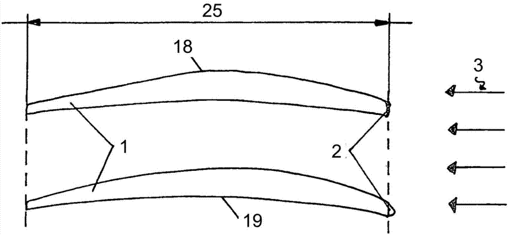
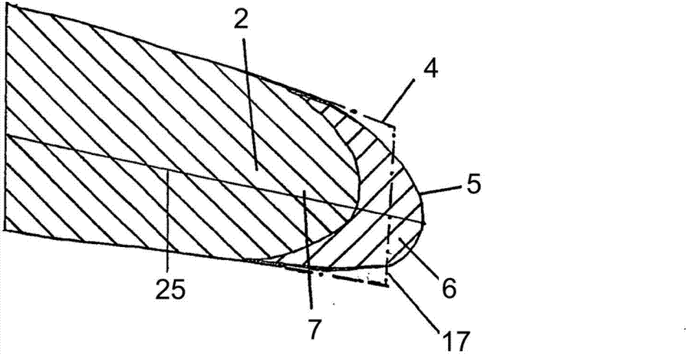
[0028] figure 1 Two compressor blades 1 , so-called fan blades, of a first compressor stage of an aircraft power plant are schematically shown in . Two compressor blades 1 are arranged one above the other, wherein the air flow 3 flows in from the right during operation. The compressor blades 1 each have an upper suction side 18 and a lower pressure side 19 as well as an inlet edge 2 , also referred to as a leading edge, facing the air flow 3 . The length from the inlet edge 2 of the compressor blade 1 to the outlet edge of the compressor blade 1 is the chord length 25 or also referred to as “chord width” of the compressor blade. The upper compressor blade 1 is damaged and shortened by erosion in the region of the entry edge 2 , the lower compressor blade 1 has been repaired by the repair method according to the invention and no longer has this damage. exist figure 2 The entry edge 2 is shown enlarged. In this case, the state of the entry edge before the repair according t...


PUM


Abstract

A method for recontouring a blade of a gas turbine includes systematically melting a portion of a leading edge of the blade using an energy beam so as to form a new contour of hardened material substantially without incorporating additional material.

Description

technical field [0001] The invention relates to a method for trimming compressor or turbine blades for gas turbines having the features of the preamble of claim 1 . Background technique [0002] Components in gas turbines, in particular in aircraft power plants, are subject to wear during operation by erosive substances, for example by sand or dust or ice. In the front part of the gas turbine, ie in the region of the compressor, erosion usually leads to a flattening of the flow entry edges (leading edges) of the compressor blades. In their unworn shape, the compressor blade has an aerodynamically optimized profile which is disadvantageously changed by wear. As a result of this deterioration of the aerodynamic profile, the efficiency of the gas turbine is lost, that is to say the gas turbine requires more fuel for the same power. From an economical point of view, therefore, resistance to compressor blade wear, in particular aerodynamically optimized blade geometry degradati...

Claims


Application Information

Patent Timeline
Patent Type & Authority Applications(China)
IPC IPC(8): B23P6/00F01D5/00B23K26/00
CPCF01D5/005B23P6/002Y02T50/671F05D2230/80B23K2201/001Y02T50/673B23K26/0081B23K26/0075B23K26/0006B23K26/354B23K26/3576B23K2101/001B23K2101/34B23K2103/14B23K2103/26B23K2103/50Y02T50/60Y10T29/49318Y10T29/49748
Inventor S·策纳
Owner LUFTHANSA TECH AG
Learn More